RX-DV3SL
1-7
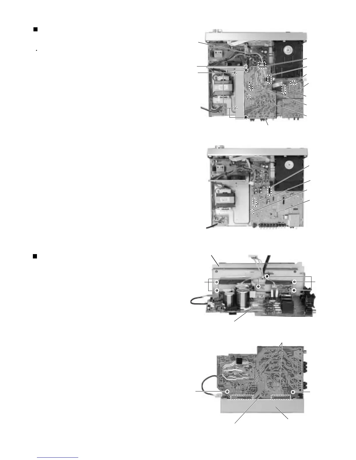
Remove the six screws marked H attaching the heat
sink.
Unsolder the two p
ower ICs solder points
attaching
the rear side of the amplifier board.
Pull out the amplifier board from the bracket hooks
on the heat sink.
1.
2.
3.
Removing the power ICs
(See Fig.13, 14)
Prior to performing the following procedures, remove
the top cover, and rear panel.
Disconnect the amplifier board from the connector
CN201.
Disconnect the amplifier board from the connector
CN212 on the main board.
Disconnect the amplifier board from the wire
connected to the connector CN231 and CN241 on
the main board.
Disconnect the screws marked F frome the ground
wire attaching the amplifier board on the fan bracket.
Disconnect the four screws G attaching the amplifier
board on the body.
1.
2.
3.
4.
5.
Removing the amplifier board
(See Fig.11, 12)
Fig.11
Fig.12
Fig.14
Fig.13
Amplifier board
rear side
Heat sink
H
H
Power ICs solder points
Heat sink
Fook
Fook
Amplifier board
DSP
board
Amplifier
board
CN201
CN612
CN602
Tie
band
CN212
F
G
CN231
CN241
CN231
CN241
CN212
Main
board

 Loading...


