1-9
1.8.2 Service position <DV SIDE>
<Removal>
(1) Remove the top cover and bracket.
(2) Remove the front panel assembly.
(3) Remove the mechanism assembly (DV side) together
with the base (2).
(4) Remove the DV Main board assembly.
Note:
•
Place an insulation sheet on the mechanism assembly
(VHS side), then remove the DV Main board assembly
and place it on the insulation sheet.
When removing the DV Main board assembly, only re-
move a connector CN1002 out of four.
Take care not to damage the parts during operating.
Table 1-8-2
SYMBOL CONNECTOR (WIRE) CONNECTIONS
PIN No
PATCH CORD
I / II 1 MAIN CN7507 — JACK CN7002 16 A
I / II 2 MAIN CN3011 — DISPLAY CN7001 18 B
I 3 MAIN CN703 — DV MAIN CN3501 6 —
I 4 MAIN CN7508 — REGULATOR CN5322 13 C
I 5 MAIN CN7509 — REGULATOR CN5321 15 D
I 6 MAIN CN2601 — DV MAIN CN3701 8 —
I / II 7 MAIN CN3014 — DV MAIN CN1002 6 E
II 8 DV MAIN CN1502 — SENSOR 15 F
II 9 P/R MDA CN5002 — DV MAIN CN2001 26 G
II 10 P/R MDA CN5506 — DV MAIN CN1501 20 H
II 11 REGULATOR CN5324 — P/R MDA CN5501 5 —
Board to Board Wire
A PTU94022-16 QUQ112-1840CG
B PTU94022-18 QUQ112-1640CG
C PTU94022-13 QUQ212-1340CG
D PTU94022-15 QUQ212-1540CG
E YTU94072-06 QUQ210-0640CG
F YTU94074-15 QUQ105-1540AA
G YTU94074-26 QUQ105-2640AA
H YTU94074-20 QUQ105-2040AA
Table 1-8-3
< Installation >
For the PATCH CORDS, see Table 1-8-3.
The patch cords that are indicated in Table 1-8-3 are in one
package.
(1) Connect a PATCH CORD to the FPC, and connect the
end to the connector CN1002.
(2) Connect PATCH CORDS to the three connectors/FPCs
(CN5506/CN5002/CN1502).
(3) Place the mechanism assembly (DV side) on the origi-
nal position and connect the four wires/FPCs/connectors
(CN5501/CN5506/CN5002/CN1502).
(4) Connect PATCH CORDS to the two FPCs of the FRONT
PANEL ASSEMBLY, and connect the ends to the
CN7507 and CN3011.
Table 1-8-4 Connection of Connectors
Fig. No.
Screw Hook, etc. Connector Note
(Page)
(1)
Top cover,
COM1 9 2 + 1 0 —
Bracket (1-3) (No.1-9) (L1,2)
(2) Front
COM2 0 8 2
panel
(1-3) (L3) (CN7507/ —
assembly
CN3011)
(3)
Mechanism D1 4 0 4
(DV SIDE)/ (1-7) (No.1-4) (CN1502/
BASE (2) CN5002/ —
CN5506/
CN5501)
(4) DV Main
D6 4 0 1
Note
board
(1-8) (No.17-20) (CN1002)
assembly
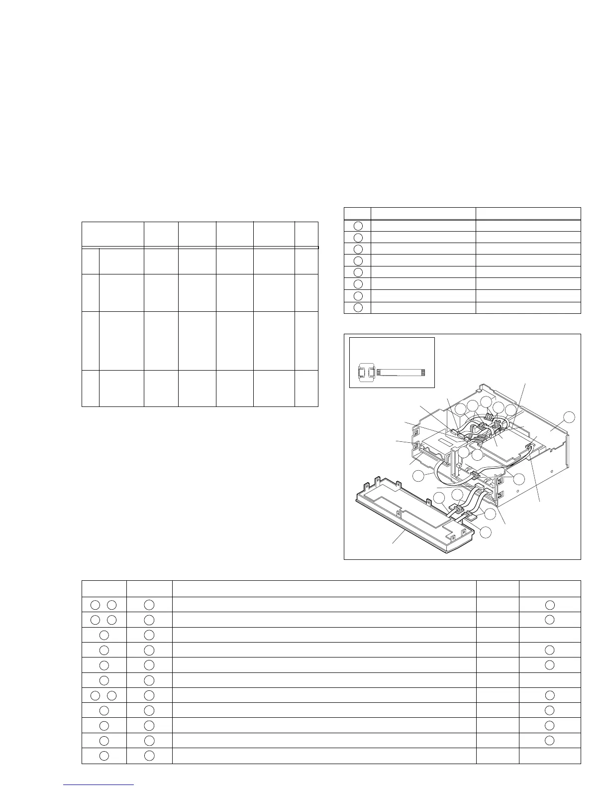
Fig. 1-8-2 Service position <DV side>
B
A
8
2
1
7
9
F
10
7
11
H
G
Insulation sheet
DV Main board
assembly
CN7507
CN1501
CN1502
CN5506
CN5002
CN5501
CN3011
BASE (2)
DV mechanism
assembly
Front panel assembly
PATCH CORD
PTU94017B
E
CN2001
CN1002