2-17
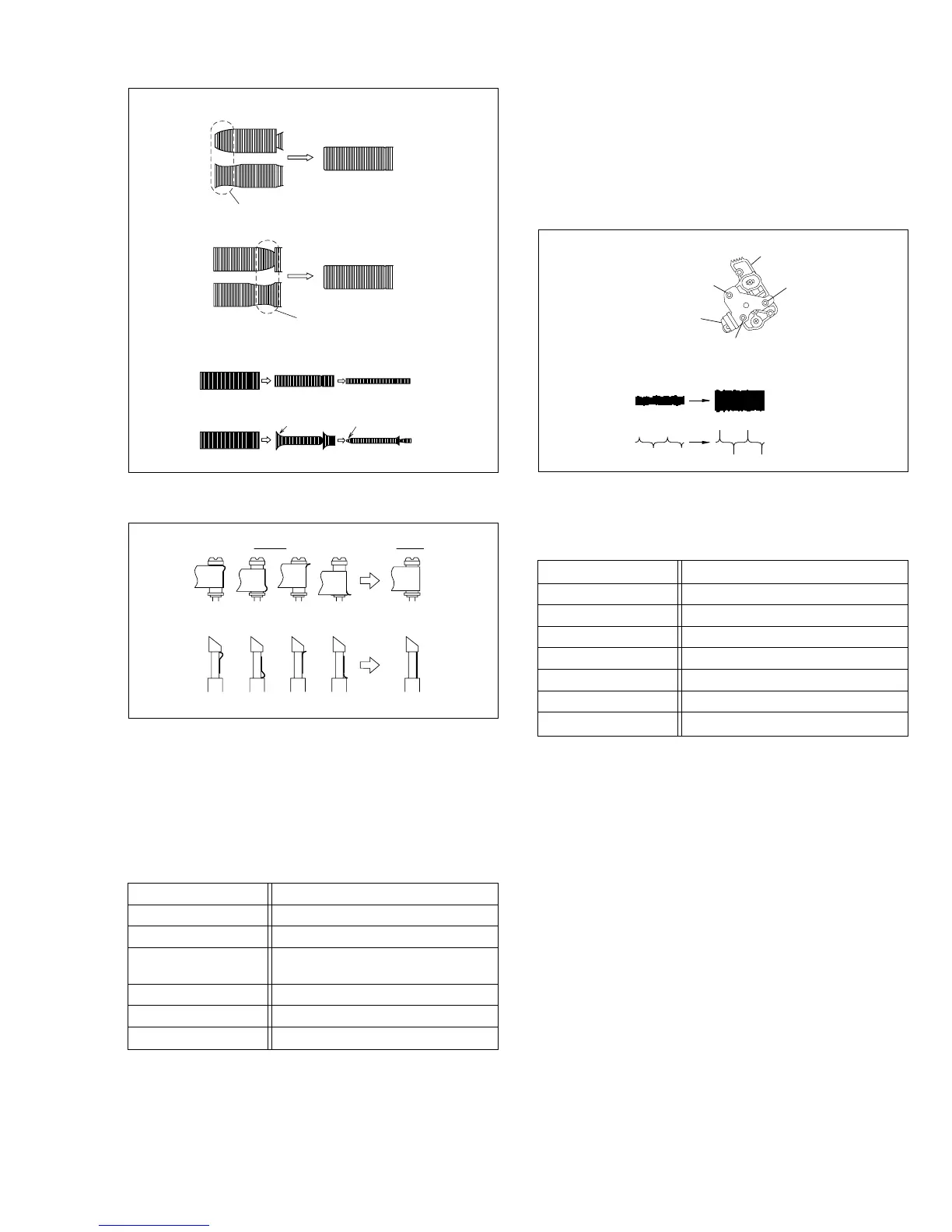
Fig. 2-3-1d
(a) Guide roller
(b) Guide pole
Improper
Proper
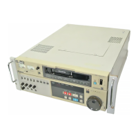
Fig. 2-3-1c
A
B
C
D
Level drop at the guide roller (supply side)
Level drop at the guide roller (take-up side)
• Proper waveform variation: Always flat
• Improper waveform variation:
Higher Lower
2.3.2 Checking/Adjustment of the Height and Tilt of the
Audio Control Head
Note:
• Set a temporary level of the height of the A/C head in
advance to make the adjustment easier after the A/C
head has been replaced. (See Fig.2-2-6c.)
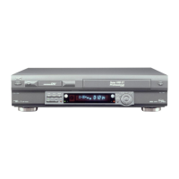
(2)
(3)
(1)
AUDIO OUT
Head base
Audio control head
CTL. P
Fig. 2-3-2a
(1) Play back the alignment tape (A).
(2) Apply the external trigger signal to D.FF (E), to observe
the AUDIO OUT waveform and Control pulse waveform
at the measuring points (D1) and (D2) in the ALT mode.
Signal (A) •
Alignment tape(SP, stairstep, PAL) [MHPE]
Mode (B) • PB
Equipment (C) • Oscilloscope
Measuring point (D1) • AUDIO OUT terminal
(D2) • TP4001 (CTL. P)
External trigger (E) • TP111 (D.FF)
Adjustment part (F) • A/C head [Mechanism assembly]
Specified value (G) • Maximum waveform
2.3.3 Checking/Adjustment of the Audio Control Head
Phase (X-Value)
Signal (A1) •
Alignment tape(SP, stairstep, PAL) [MHPE]
Mode (B) • PB
Equipment (C) • Oscilloscope
Measuring point (D) • TP106 (PB. FM)
External trigger (E) • TP111 (D.FF)
Adjustment part (F) •
A/C head base [Mechanism assembly]
Specified value (G) • Maximum V.PB FM waveform
Adjustment tool (H) • A/C head positioning tool [PTU94010]
(1) Play back the alignment tape (A1).
(2) Apply the external trigger signal to D.FF (E), to observe
the V.PB FM waveform at the measuring point (D).
(3) Press the channel buttons (+, –) simultaneously to enter
the manual tracking mode. This also brings tracking to
the center (centre).
(4) Loosen the screws (4) and (5), then set the A/C head
positioning tool to the innermost projected part of the A/
C head. (See Fig. 2-3-3a.)
(5) Turn the A/C head positioning tool fully toward the cap-
stan. Then turn it back gradually toward the drum and
stop on the second peak point position of the V.PB FM
waveform output level. Then tighten the screws (4) and
(5).
(6) Perform the tracking operation and make sure that the
V.PB FM waveform is at its maximum.
If it is not at maximum, loosen the screws (4) and (5),
and turn the A/C head positioning tool to bring the A/C
head to a position, around where the waveform reaches
its maximum for the first time. Then tighten the screws
(4) and (5).
(3) Press the channel buttons (+, –) simultaneously to enter
the manual tracking mode. This also brings tracking to
the center (centre).
(4) Adjust the AUDIO OUT waveform and Control pulse
waveform by turning the screws (1), (2) and (3) little by
little until both waveforms reach maximum. The screw (1)
and (3) are for adjustment of tilt and the screw (2) for azi-
muth.