2-4
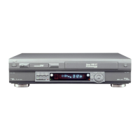
Guide rail Roller cam assembly
L2L1
Opener guide
Door
opener
Drive gear
Cassette housing bracket
Limit gear
Worm gear
Belt (loading motor)
Loading motor
R2
R3
R5
R4
R1
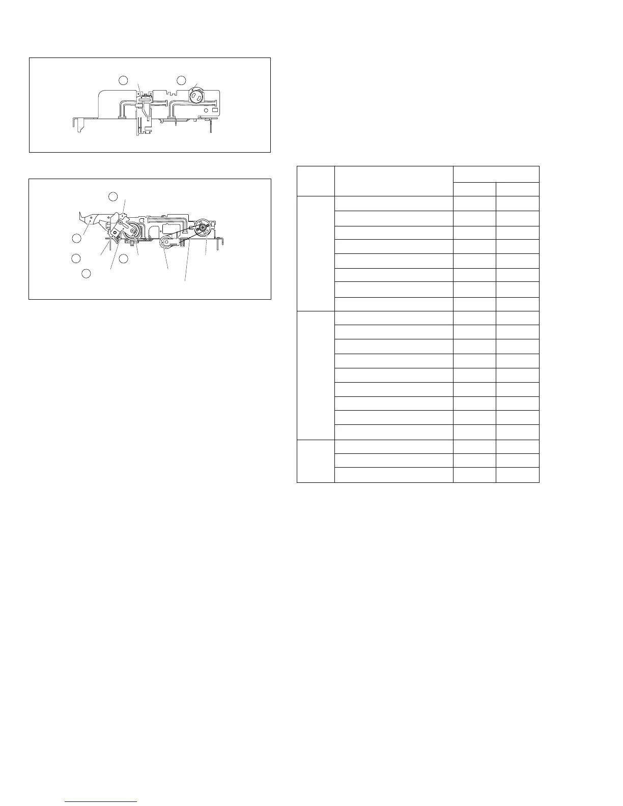
Fig. 2-1-5c Mechanism assembly left side
Fig. 2-1-5d Mechanism assembly right side
5. Disassembling procedure table
The following table indicates the order in which parts are re-
moved for replacement. To replace parts, remove them in
the order of 1 to 18 as shown in the table. To install them,
reverse the removal sequence.
The symbols and numbers preceding the individual part
names represent the numbers in the “Location of major me-
chanical parts” table. Also, the “T”, “B”, and “T/B” on the right
of each part name shows that the particular part is removed
from the front, from the back, and from both sides of the
mechanism, respectively.
2. Cleaning
Regular cleaning of the transport system parts is desirable
but practically impossible. So make it a rule to carry out clean-
ing of the tape transport system whenever the machine is
serviced.
When the video head, tape guide and/or brush get soiled,
the playback picture may appear inferior or at worst disap-
pear, resulting in possible tape damage.
(1) When cleaning the upper drum (especially the video
head), soak a piece of closely woven cloth or Kimu-wipe
with alcohol and while holding the cloth onto the upper
drum by the fingers, turn the upper drum
counterclockwise.
Note:
• Absolutely avoid sweeping the upper drum vertically
as this will cause damage to the video head.
(2) To clean the parts of the tape transport system other than
the upper drum, use a piece of closely woven cloth or a
cotton swab soaked with alcohol.
(3) After cleaning, make sure that the cleaned parts are com-
pletely dry before using the video tape.
3. Lubrication
With no need for periodical lubrication, you have only to lu-
bricate new parts after replacement. If any oil or grease on
contact parts is soiled, wipe it off and newly lubricate the
parts.
Note:
• See the “mechanism assembly” diagram of the parts
list for the lubricating or greasing spots, and for the
types of oil or grease to be used.
~1000H ~2000H
Upper drum assembly
¤R R
A/C head
¤R ¤R
Lower drum assembly
¤¤R
Pinch roller arm assembly
¤¤
Full erase head
¤¤
Tension arm assembly
¤¤
Capstan motor (Shaft)
¤¤
Guide arm assembly
¤¤
Capstan motor
R
Capstan brake assembly
R
Main brake assembly
R
Belt (Capstan)
RR
Belt (Loading motor)
R
Loading motor
R
Clutch unit
R
Worm gear
R
Control plate
R
Brush
¤R ¤R
Tension brake assembly
RR
Rotary encoder
R
4. Suggested servicing schedule for main components
The following table indicates the suggested period for such
service measures as cleaning,lubrication and replacement.
In practice, the indicated periods will vary widely according
to environmental and usage conditions.However, the indi-
cated components should be inspected when a set is brought
for service and the maintenance work performed if neces-
sary. Also note that rubber parts may deform in time,even if
the set is not used.
Operation Hours
System Parts Name
¤
: Cleaning
R
: Inspection or Replacement if necessary
Table 2-1-5a
Other Drive Tape transport