r
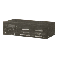
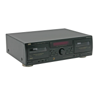
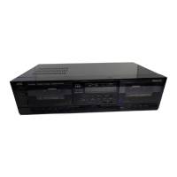
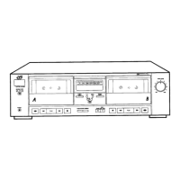
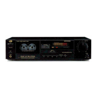
TD-X321
NarcEto^tru
i
3. Routine oÍ electrical circuit adiustment
:
Perform
the tape
transport
checks and head azimuth adiustment
before
following
checks and adjustments.
Adjustment
should
be
per:formed
in the
order
of-adjustment steps.
ln
the steps
marked with an
asterisk
(
*
),
adiustment should
be
performed
after replacing
the
heads.
Perform this adjustment
with
the N R
switch set
to OF
F.
No. Item Check
point
Adiustment
position
Condition
Adjustment,
Conf
irmation
*1
Playback
level
I
LIN
E
OUT
I
adiustment
l
(When
the head is
replaced, adjust
playback
level.)
L:
VR102
R : VR2O2
vTT724 1)
Plarr back
the vTT724
te§t tape.
2) Adjust VR102,
VR202
so
that LINE
OUT
level
be-
comes
-8
dBs.
3) Headphone
OUT:
-24
dBs
t
3
dB
4) DIN
OUT
:
-8
dBs
t2
dB
(TD-X321G)
*2
Playback
frequency
response
adjustment
L: VR101
R
:
VR201
TMT735 1
)
Play back,the
TMT735
test
tape.
2) Adjust VR101, VR201 so
that LINE OUT level
be-
comes
+0.5
+
0.5
dB
(1
kHz
-
12.5
kHz).
*3
Bias
frequency
adiustment
Connect the
body
of
c81
7.
L801 METAL tape 1) Connect the
frequenqy counter
to the LINE
OUT
terminals.
2)
Adjust
L801
so
that the counter
reads 95
kHz.
r
Standard
value
:
95
kHz
l
2kHz
*4
Adjustment
of HX
pro.
Rl47
R247
L105
L205
METAL tape
1
)
Record
with,
METAL tape
and
play
it
back.
2) Adiust Ll05 and L205 to
minimize
voltages at
R147
and
R247 respectively
with
the
tape being
played
back.
*5
Rec/PB
frequency
response
adjustment
LINE IN
LINE
OUT
L
: VR104
R : VR204
NORMAL
Blank tape
1)
NR
switch: OFF
2) Record a 1.25
kHz
signa!
at an input
reference level
of
-20
dB.
3)
Record
1.25kHz
and
12.5kHz
signals
and
play
them
back.
4)
Adjust VR104 and
VR204
so
that
the
deviations of
1.25
kHz
and 12.5kHz
outputs satisfy
the standard
values
with respect to 1
kHz output.
o
With respect to 1
kHz
reference
At 12.5
kHz
:
0.5
t
0.5
dB
(Adjustment)
*^
o
Recording
gain
adjust-
ment
LINE IN
LINE OUT
L
: VR103
R : VR203
NORMAL,
CrO2,
METAL
Blank tapes
1) Apply
a
1
kHz
signal
to
the LINE
lN terminals.
2) Adjust VR103,
VR203
so
that LINE OUT
terminal
level
becomes
-8
dBs
t
0.5
dB.
o
CrO2 :
-B
dBs
+
2
dB
(Confirm)
o
METAL:
-8
dBs
t
2 dB
(Confirm)
7
Rec/PB
distortion
check
LINE
IN
LINE OUT
NORMAL,
CrO2,
METAL
Blank tapes
1) Record a
1 kHz,
-8dBs
signal
through LINE OUT
terminals.
2l
PlaV back the recorded
part.
3) Check
thp output
with
a
distortion meter to see if the
value
conforms to the standard
value.
o
Standard
value
INORMALI
: Less than 2%THD
lCr0z
I
:
Les
than 3%
THD
IMETALI
: Less than2o/oTHD
1 6
(No.
4305)
 Loading...