1-10 (No.MB187)
3.1.3 Removing the DVD mechanism assembly
(See Figs.5,6 and 8)
• Remove the metal cover.
(1) From the right side of the DVD mechanism assembly, push
the slide cam and pull the tray assembly out of the main
body in the direction of the arrow. (See Fig.5.)
(2) From the front side of the main body, remove the CD fitting
assembly from the tray assembly in the direction of the ar-
row and push in the tray assembly as before. (See Fig.6.)
(3) From the top side of the main body, disconnect the card
wires from the connectors (CN422
to CN426) on the main
board. (See Fig.8.)
(4) Disconnect the wire from the connector CN430
on the main
board. (See Fig.8.)
(5) Remove the three screws D attaching the DVD mechanism
assembly on the chassis base. (See Fig.8.)
Reference:
When attaching the DVD mechanism assembly, align the
holes of the chassis base to the projections d of the DVD
mechanism assembly. (See Fig.8.)
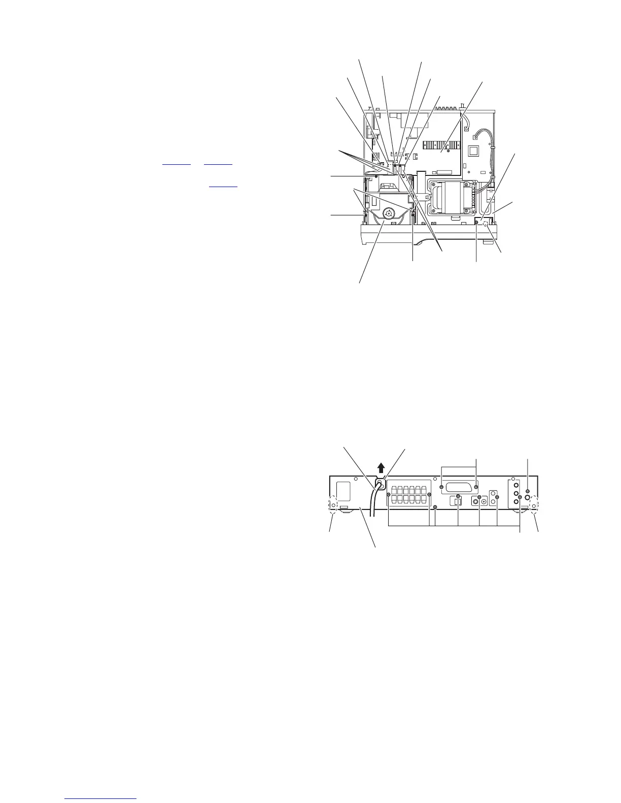
3.1.4 Removing the HP terminal board
(See Fig.8)
• Remove the metal cover and front panel assembly.
(1) From the top side of the main body, remove the screw E at-
taching the HP terminal board on the chassis base.
(2) Take out the HP terminal board from the main body.
Reference:
When attaching the HP terminal board, align the hole on the
HP terminal board to the projection e of the chassis base be-
fore attaching the screw E.
Fig.8
3.1.5 Removing the rear panel
(See Fig.9)
• Remove the metal cover.
(1) From the back side of the main body, remove the strain re-
lief attaching the power cord in the direction of the arrow.
(2) Remove the eight screws F and two screws F’ attaching
the rear panel. [B/E/EN/EV/EE version]
(3) Remove the eight screws F attaching the rear panel. [A
version]
(4) Release the engagement sections f and remove the rear
panel from the main body.
Fig.9
d
D
D
CN425
CN422
CN423
CN430
CN424
CN426
Card
wires
Wire
D
Card wires
Main board
HP terminal
board
e
E
Chassis
base
DVD mechanism assembly
F
Rear panel
F
Strain relief
Power cord
f
F'
 Loading...