21
䡵 Alarm input terminal
Connects to sensors such as infrared sensors,
door sensors, metal sensors and manual switches.
● To prevent noise from entering the internal circuit, supply
non-voltage contact signal to the alarm input terminal.
● Do not supply voltage.
● When the contact is short (MAKE) or open (BREAK) on
the menu, you can set it to Alarm.
● Supply such that the alarm signal continues for at least
more than 200 ms. The alarm signal may not be
recognized if it is less than 200 ms.
䡵 Alarm output terminal
Connects to alarm devices such as alarm,
indicator, light or buzzer
● Alarm output 1 terminal is the contact output. When there
is an alarm, the OUT1 NOP-COM will become short
(MAKE) and OUT1 NCL-COM will become open
(BREAK).
● Alarm output 2 terminal is an open collector output
insulated with photo coupler.
● During an alarm, it is ON.
● As this terminal is polarized, be sure to connect it such
that the voltage of the + terminal is higher than that of the
– terminal.
● It will be damaged if reverse voltage is supplied.
Memo :
● When alarm is switched ON/OFF, a sound will be
produced from the alarm output 1 relay. If you mind the
sound, use alarm output 2 terminal. Be sure not to exceed
the rating.
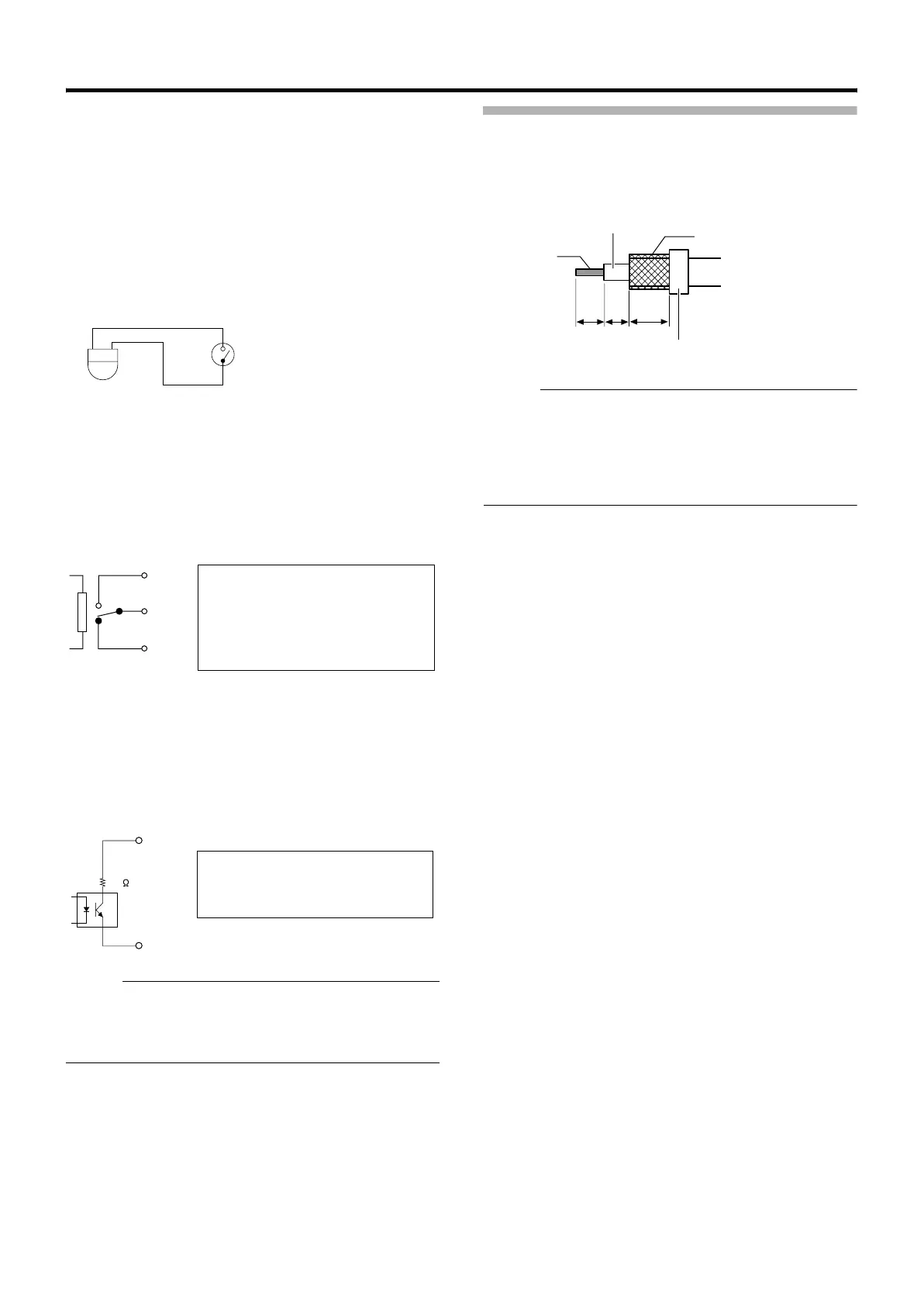
Connecting the coaxial cable
Connecting a RG-59 coaxial cable.
Treat the extremity of the coaxial cable as shown below
before connecting it.
7 mm
4 mm
8 mm
Polyethylene
Insulating tape
Mesh shield wire
Core wire
Memo :
● If a RG-11 coaxial cable is used it cannot be connected
directly to the terminal board. To use such a cable,
connect a RG-59 cable to the camera and then connect
the RG-11 cable to the RG-59 cable.
● Turn the mesh shield wire over and insulate it so that it will
not fray and cause short circuit.
IN
GND
N.OPEN
COM.
N.CLOSE
Rating:
Max. applied voltage: DC 30 V or
AC 24 V
Max. applied current: 1 A
Contact life : 100,000 times
OUT +
OUT -
22
Rating:
Max. applied voltage: DC 20 V
Max. driving current : 25 mA
TK-C686E_EN.book Page 21 Tuesday, December 4, 2007 4:45 PM

 Loading...