:
Observe the following points when connecting
components together:
● Turn all the components off before proceeding.
● Read the instruction manuals of all components before
proceeding.
● For the types and lengths of connection cables, see
[Cable Connection] (A Page 20)
● Do not connect the control signal cables in a loop.
10
Connection/Installation
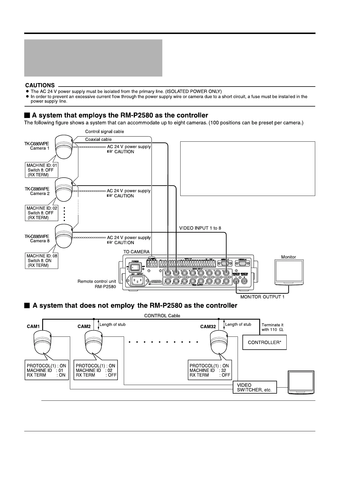
Note :
● Set the TERM switch of CAM1 to ON, and terminate at the controller with a resistance of 110 K.
● Set the TERM switches of the other cameras to OFF.
● As long as there are no specifications, set PROTOCOL (2) to AOFFB.
● An AC 24 V power source must be supplied to each camera.
System Connection
Example
TK-C686E_EN.book Page 10 Tuesday, December 4, 2007 4:45 PM
 Loading...