9
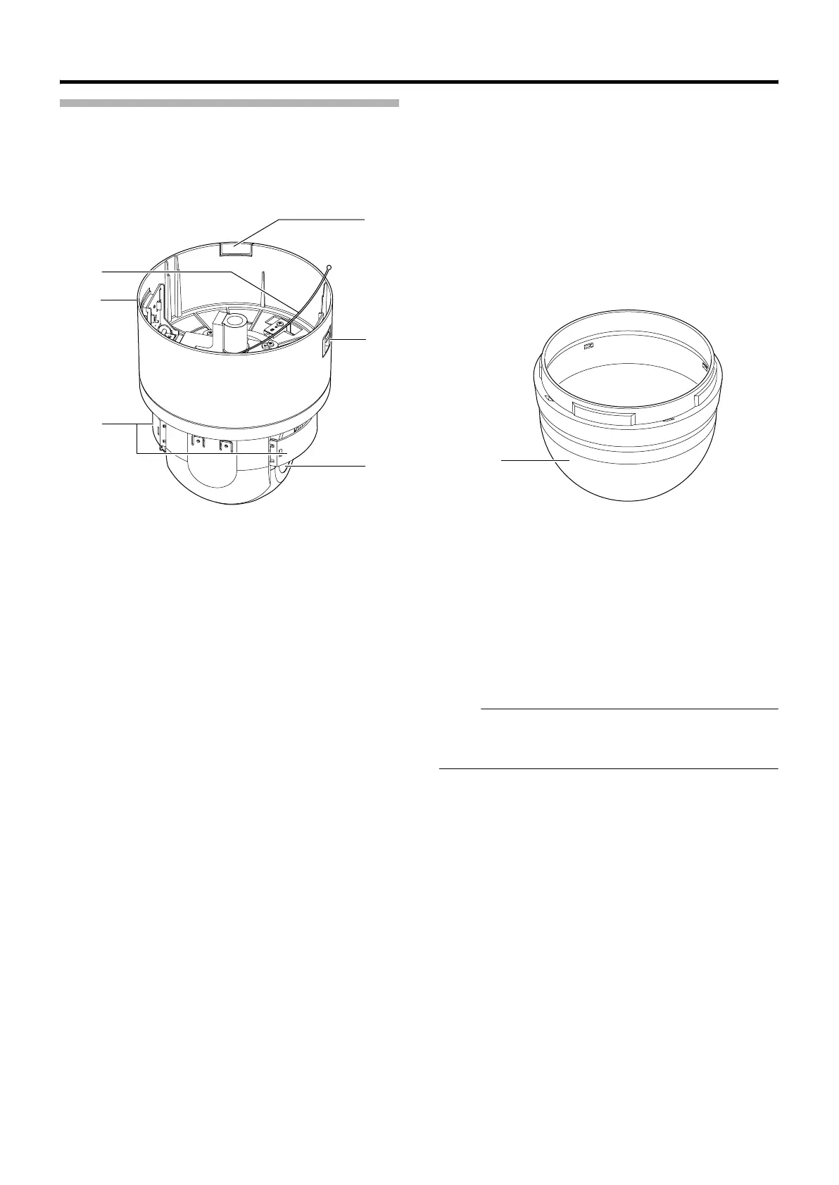
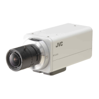
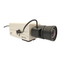
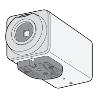
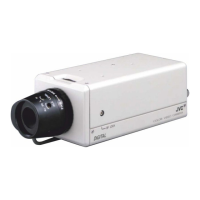
Camera
I Fixing holes (x3)
This hole is for mounting the ceiling clamping bracket to the
ceiling or the ceiling recessed bracket (
WB-S685U: Sold
separately).
J Setting Switch
This switch allows you to configure settings such as protocol
and SYNC.
(A Page 17)
K Machine ID Setting Switch
When the communication system is RS-485 multi DROP
such as the RM-P2580 system, a machine ID will be set
for every camera. (A Page 18)
L Backup switch
This switch cannot be used.
M Power lamp
The lamp lights up in green when AC24V power is turned on.
N Camera connection terminal (female)
This connects to the connection terminal (male) of the
camera.
O Fall Prevention Wire
This attaches to the fall prevention wire fixing bracket F of
the camera.
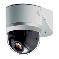
P Front Mask
Q Lens
Lens cannot be replaced.
R Camera fixing lock knob (x2)
This knob secures the camera to the ceiling so that it does
not fall.
S Camera fixing lock knob (x2)
This knob secures the camera to the ceiling so that it does
not fall.
T Cable cover
Remove the cover to pull the cables from the side of the
camera and mount the camera.
(A Page 14)
U Dome Cover
The dome cover is a delicate object. Handle it with care.
Note :
● Do not peel off the protective sheet which is attached at
shipment, until the dome cover is mounted on the main
unit. (A Page 15)
R
O
Q
P
S
R
T
TK-C686E_EN.book Page 9 Tuesday, December 4, 2007 4:45 PM