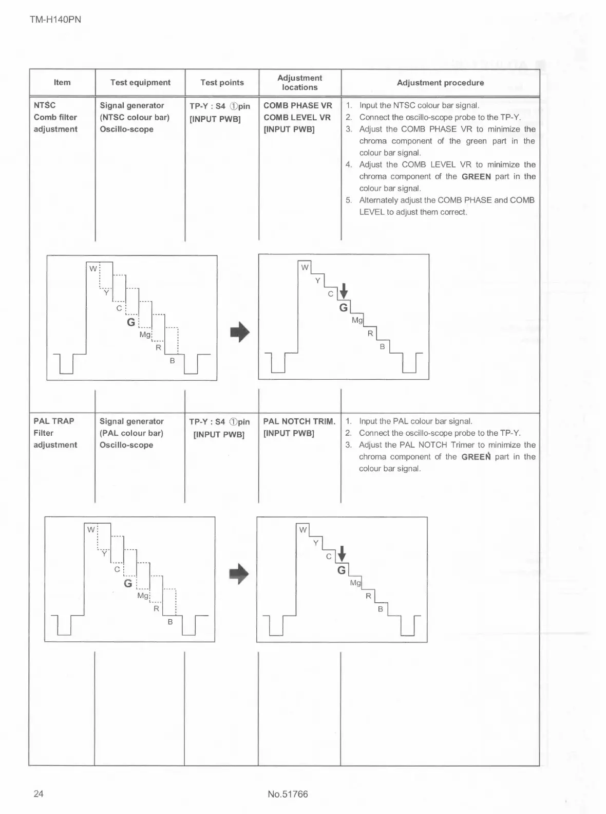
TM-H140PN
Item
NTSC
Comb filter
adjustment
PAL TRAP
Filter
adjustment
24
w
w
Test equipment
Signal generator
(NTSC colour bar)
Oscillo-scope
y }
Mg: :
'"i~-1
Signal generator
(PAL colour bar)
Osei llo-scope
y }·
B
Mg: :
,.R. !
B
Test points
TP-Y: S4 (])pin
[INPUT PWB]
+
TP-Y : S4 (])pin
[INPUT PWB]
Adjustment
locations
COMB PHASE VR
COMB LEVEL VR
[INPUT PWB]
PAL NOTCH TRIM.
[INPUT PWB]
No.51766
1.
2.
3.
Adjustment procedure
Input the NTSC colour bar signal.
Connect the oscillo-scope probe to the TP-Y.
Adjust the COMB PHASE VR to minimize the
chroma component of the green part in the
colour bar signal.
4. Adjust the COMB LEVEL VR to minimize the
chroma component of the GREEN part in the
colour bar signal.
5. Alternately adjust the COMB PHASE and COMB
LEVEL to adjust them correct.
1. Input the PAL colour bar signal.
2. Connect the oscillo-scope probe to the TP-Y.
3. Adjust the PAL NOTCH Trimer to minimize the
chroma component of the GREE~ part in the
colour bar signal.
 Loading...