TM-H140PN
Item
Test equipment Test points
Adjustment
Adjustment procedure
locations
WHITE Signal generator W06 R DRIVE 9300
•
Low light white balance adjustment have been
BALANCE (Resolution pattern) W07 B DRIVE 9300
correct finished.
(High light) [SERVICE MENU]
1. Input the resolution pattern to VIDEO input.
9300K Colour Analyzer or
2. Select the WHITE BALANCE BLOCK from the
adjustment
Colour temperature
SERVICE MENU .
meter
3. Select the 93-D mode (High light 9300 mode).
4. Apply the sensor of the Colour temperature
meter to the CRT surf ace,
part of the 100%
white, adjust the R drive or B drive to setting
9300K (x=0 .283, y=0.297) .
5. Exit the SERVICE MENU by pressing the MENU
key.
6.
Check the white balance tracking is optimum
when CONTRAST and BRIGHT are up and
down.
Bright Signal generator
S01 (BRIGHT)
•
Low light white balance adjustment have been
adjustment (Sprit colour bar)
[SERVICE MENU]
correct finished .
1. Input a sprit colour bar signal.
2. Select the SIGNAL BLOCK from the SERVICE
MENU.
3. Select the S01 item .
4.
Adjust S01 to where the sprit colour bar 0%
black component faintly brightens .
5. Check it to on and off the
screen display by
turning the "DISP" switch.
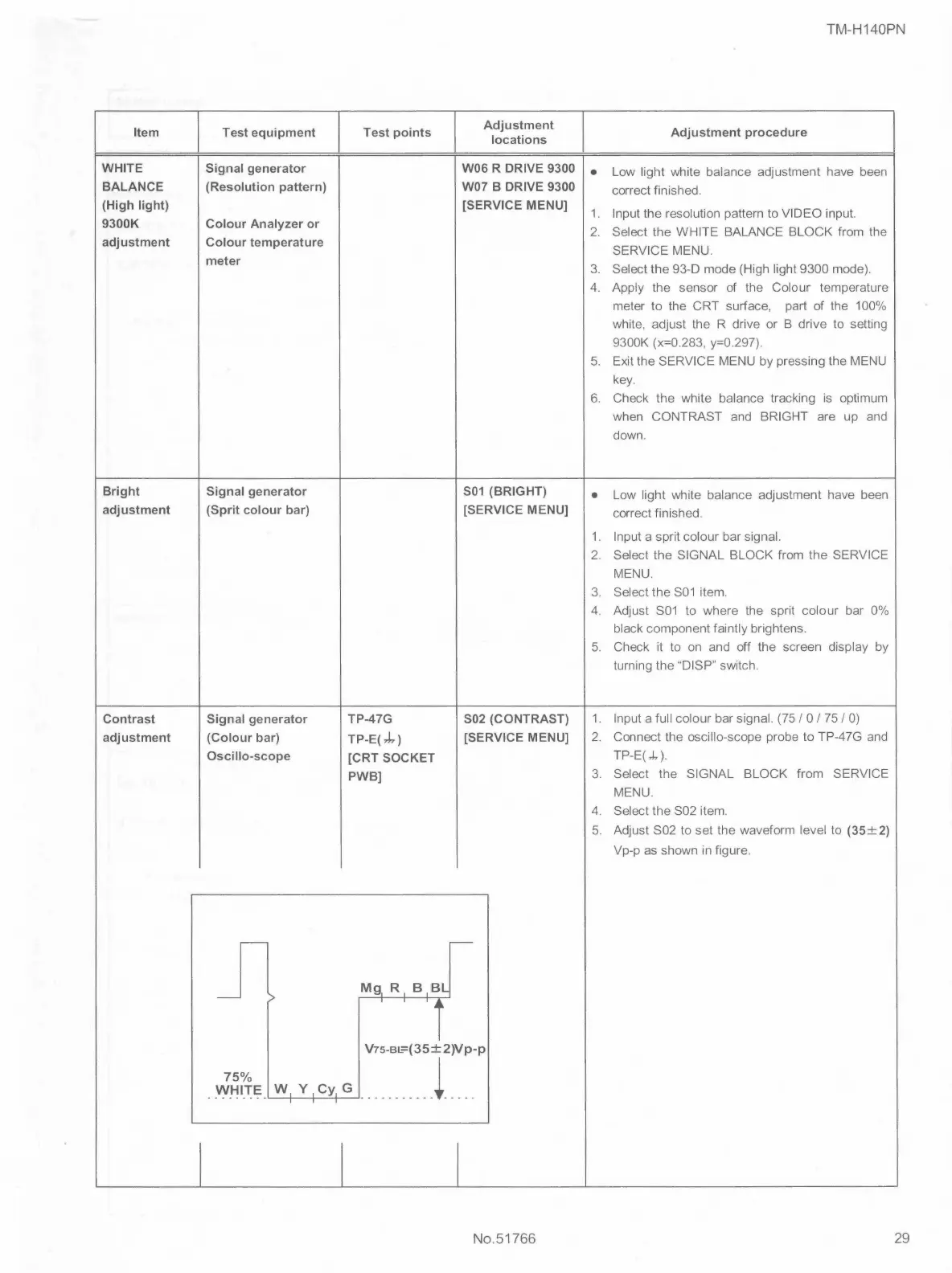
Contrast Signal generator TP-47G S02 (CONTRAST)
1. Input a full colour bar signal. (75 / 0 / 75 / 0)
adjustment (Colour bar)
TP-E(,.).,)
[SERVICE MENU]
2.
Connect the oscillo-scope probe to TP-47G and
Oscillo-scope
[CRT SOCKET
TP-E( ,J, ).
PWB]
3. Select the SIGNAL BLOCK from
SERVICE
MENU.
4. Select the S02 item.
5. Adjust S02 to set the waveform level to (35±2)
Vp-p as shown in figure.
75%
WHITE W, Y ,Cy, G
I I
No.51766
29
 Loading...