TM-H140PN
■
DEFLECTION CIRCUIT ADJUSTMENT
There are 6 modes of DEFLECTION ADJUSTMENT depending upon the kind of input signals.
The adjustments must always be carried out in regular sequence given below.
DATA MODE
SERVICE NUMBER IN
SETTING DATA VALUE
SERVICE MENU
50Hz (PAL)
DO* DO*
4:3
60Hz (NTSC)
DA* DO*
+DA*
50Hz (PAL)
DB* DO*
+DB*
16:9
60Hz (NTSC)
DC* DO*
+DA* + DC*
UNDER SCAN
50Hz (PAL)
DD* DO*
+DD*
(4:3)
60Hz (NTSC)
DE* DO*
+DA*
+ DE*
• SPECIAL INDICATION
DATA MODE
SERVICE NUMBER IN
SETTING DATA VALUE
SERVICE MENU
50Hz (PAL)
DF7 DO? + DB? + DD? + DF7
UNDER SCAN
DFS
DOS + DBS + DDS + DFS
(16:9)
60Hz (NTSC)
DG7 DO? + DA?+ DC? + DE? + DG7
DGS DOS + DAS + DCS + DES + DGS
If you change the figures in the course of the adjustments by returning to the preceding steps, all adjustments come to nothing.
The screen aspect ratio 4 : 3 at 50Hz (PAL) is regarded as the reference value for all adjustments. The other values obtained in the
adjustments using other signals become the off-set values as opposed to the reference values.
Item
H.CENTER
H.SIZE
adjustment
V.CENTER
adjustment
32
Test equipment Test points
Adjustment
locations
Signal generator
D01 (H.CENTER)
(Cross-hatch D02 (H.SIZE)
pattern)
[SERVICE MENU]
SCREEN SIZE
.~ ____ 95% _ _ _
~
~
_ _ _ _ 95% ____
~
~
I
I t,,,.....-t-..--t...,,_.+,,-,.......,_+.-..-+-o.--i--,,-t-..--t---,.<l
I
I
: l----t---4-.+,,-,.......,_+,-+---+----1--t----i
I ___ __.......,....._ ........ _...._ _ __.. _ _..___.____.
~-100%
----
►
I
◄-----
100%~
PICUTURE SIZE
Signal generator
(Circle pattern)
I
I
I
I
I
I
D03 (V.CENTER)
[SERVICE MENU]
I
No. 51766
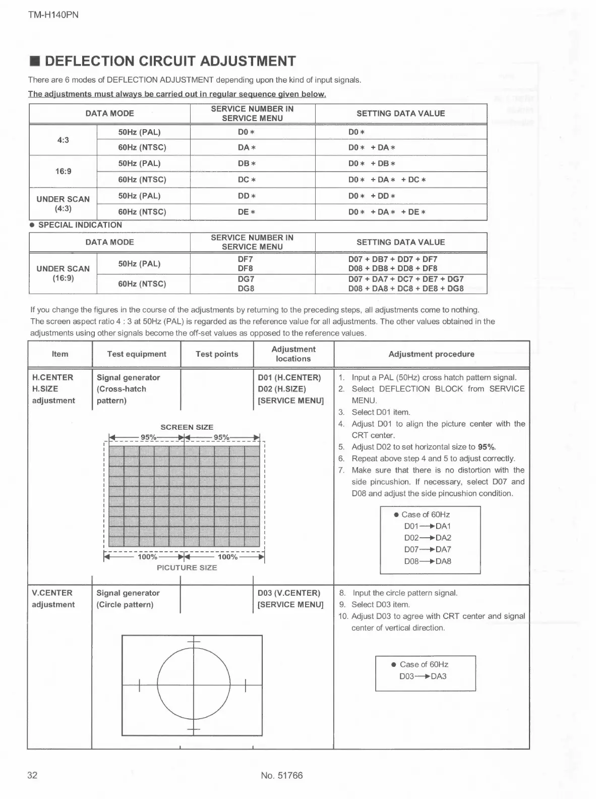
1.
2.
Adjustment procedure
Input a PAL (50Hz) cross hatch pattern signal.
Select DEFLECTION BLOCK from SERVICE
MENU.
3. Select D01 item.
4. Adjust D01 to align the picture center with the
CRT center.
5. Adjust D02 to set horizontal size to 95%.
6. Repeat above step 4 and 5 to adjust correctly.
7. Make sure that there is no distortion with the
side pincushion. If necessary, select DO? and
D08 and adjust the side pincushion condition.
• Case of 60Hz
D01--+DA1
D02--+DA2
D07--+DA7
D08--+DA8
8. Input the circle pattern signal.
9. Select D03 item.
10. Adjust D03 to agree with CRT center and signal
center of vertical direction.
• Case of 60Hz
D03--+DA3
 Loading...