■
SELF DIAGNOSIS FUNCTION
1.0UTLINE
TM-H140PN
This model includes a SELF DIAGNOSIS FUNCTION that checks the circuit operating status and in event of malfunction , displays and
stores the data in a memory. The data are stored in an I 2C memory.
Fault detection starts with the I 2C bus and is performed according to the input states of the control lines connected to the MAIN CPU.
2.USAGE
SELF DIAGNOSIS FUNCTION mode entry
(1) While press the MENU key and CHROMA key simultaneously, and push
the MAIN POWER switch on.
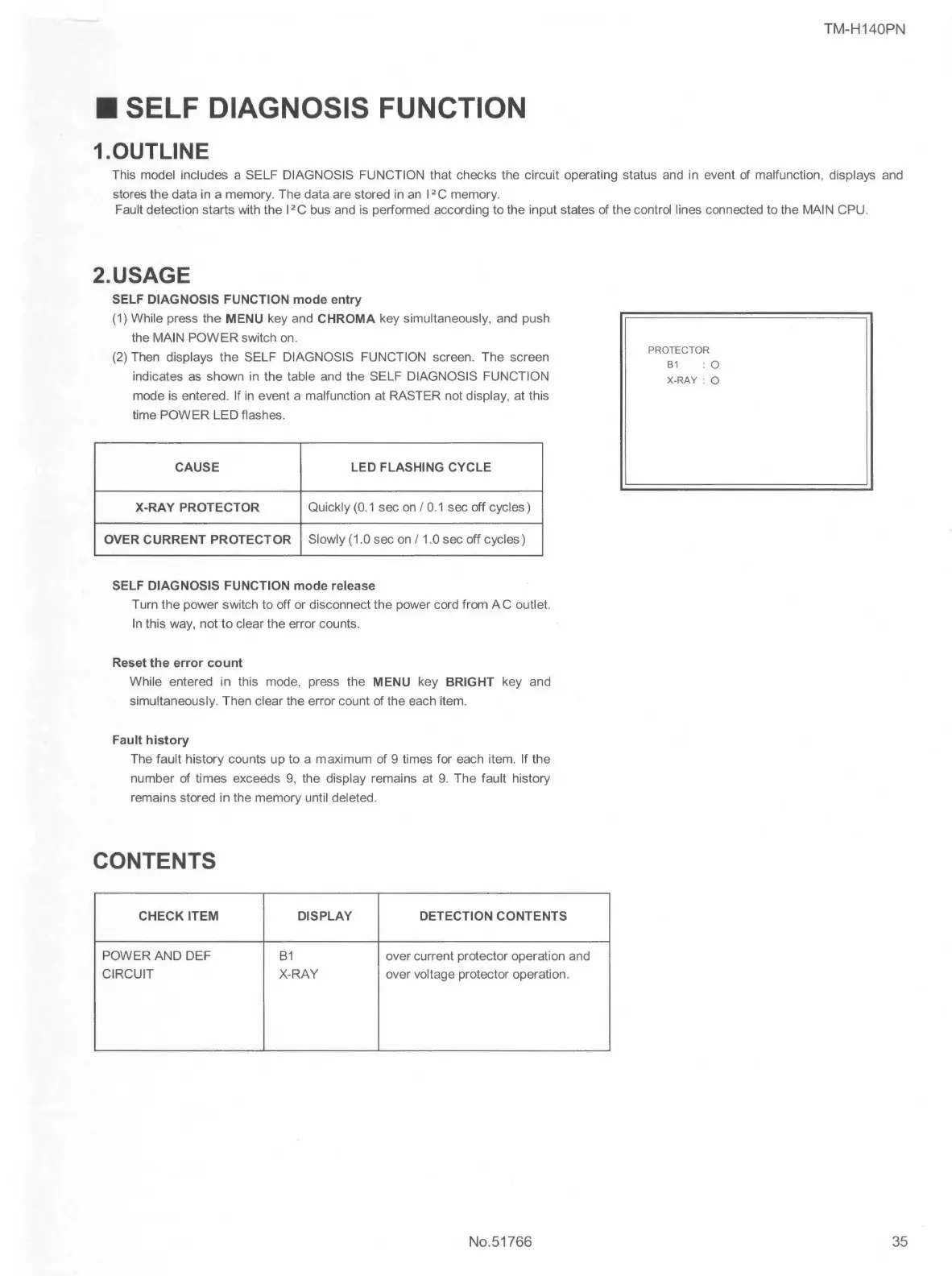
(2) Then displays the SELF DIAGNOSIS FUNCTION screen. The screen
indicates as shown in the table and the SELF DIAGNOSIS FUNCTION
mode is entered. If in event a malfunction at RASTER not display , at this
time POWER LED flashes.
CAUSE LED FLASHING CYCLE
X-RAY PROTECTOR
Quickly (0.1 sec on / 0.1 sec off cycles)
OVER CURRENT PROTECTOR
Slowly (1.0 sec on/ 1.0 sec off cycles)
SELF DIAGNOSIS FUNCTION mode release
Turn the power switch to off or disconnect the power cord from AC outlet.
In this way, not to clear the error counts.
Reset the error count
While entered in this mode, press the MENU key BRIGHT key and
simultaneously. Then clear the error count of the each item.
Fault history
The fault history counts up to a maximum of 9 times for each item. If the
number of times exceeds 9, the display remains at 9. The fault history
remains stored in the memory until deleted.
CONTENTS
CHECK ITEM DISPLAY DETECTION CONTENTS
POWER AND DEF 81 over current protector operation and
CIRCUIT X-RAY over voltage protector operation.
No.51766
PROTECTOR
81 : 0
X-RAY: 0
35
 Loading...