21
● To use the SWITCHED OUT terminal, the main power must be ON. (Unlike a bridged output, this connector outputs relocked
digital signals.)
● Signal output from the SWITCHED OUT terminal can be changed by selecting INPUT C (SDI 1) or INPUT D (SDI 2). You can
use the front panel buttons or do it via external control.
● When INPUT-A or INPUT-B is selected, this terminal outputs the signals last selected. In the standby mode, signals from the
SDI 1 connector are output.
APPENDIX: CONNECTION EXAMPLES FOR THE
SDI INPUT CARD
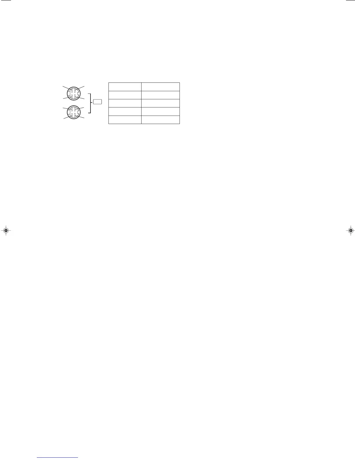
Pin No. Signal
1 GND (Y)
2 GND (C)
3Y
4C
Y/C (Mini DIN 4 pin) terminal
specification
22
LCT1025-002A-H(EN) 02.4.25, 1:31 PM24
 Loading...