(No.MB286)1-11
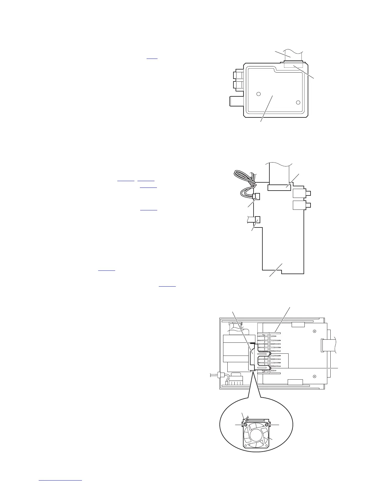
3.1.7 Removing the tuner
(See Fig.14)
• Prior to performing the following procedures, remove the side
panels L/R and rear panel.
Disconnect the card wire from the connector CN1
on the tuner.
Fig.14
3.1.8 Removing the video board
(See Fig.15)
• Prior to performing the following procedures, remove the side
panels L/R and rear panel.
(1) From the forward side of the video board, disconnect the
card wires from connectors (CN300
, CN302).
(2) Disconnect the wire to the connector CN301 on the video
board.
Reference:
After connecting the wire to the connector CN301
, fix it with the
wire holder as before.
3.1.9 Removing the fan
(See Figs.15 and 16)
• Prior to performing the following procedures, remove the side
panels L/R, front panel assembly, top cover assembly and rear
panel.
(1) From the forward side of the video board, disconnect the
wire from connector CN301
. (See Fig.15.)
Reference:
After connecting the wire to the connector CN301
, fix it
with the wire holder as before.
(2) From the back side of the main body, remove the two
screws J attaching the fan to the fan bracket B. (See
Fig.16.)
Reference:
When removing the fan with the fan bracket B, remove
the two screws K attaching the fan bracket B to the heat
sink B. (See Fig.16.)
(3) Take out the fan from the main body.
Fig.15
Fig.16
Card wire
CN1
Tuner
Video board
CN300
CN301
CN302
Heat sink B
K
Fan bracket B
J
Fan bracket B
Fan
J

 Loading...


