1-10 (No.MB286)
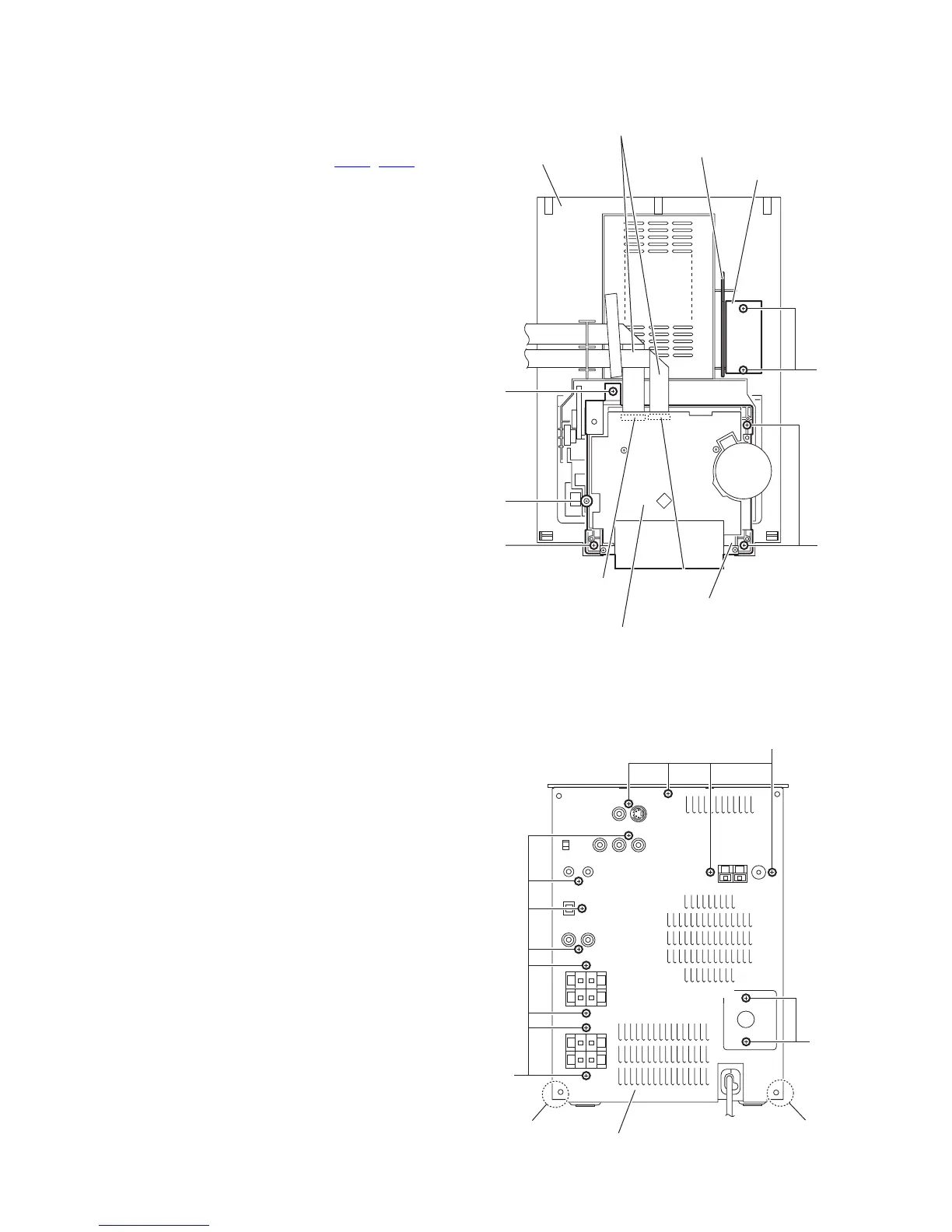
3.1.4 Removing the cassette mechanism assembly
(See Fig.12)
• Prior to performing the following procedures, remove the side
panels L/R, front panel assembly and top cover assembly.
(1) From the bottom side of the top cover assembly, discon-
nect the card wires from the connectors (CN33
, CN34) on
the head amp. & mechanism control board.
(2) Remove the four screws E and csrew F attaching the cas-
sette mechanism assembly and take out the cassette
mechanism assembly from the top cover assembly.
3.1.5 Removing the microphone amplifier board
(See Fig.12)
• Prior to performing the following procedures, remove the side
panels L/R, front panel assembly and top cover assembly.
(1) From the bottom side of the top cover assembly, remove
the two screws G attaching the echo board and remove the
echo board.
(2) Take out the microphone amplifier board from the top cover
assembly.
Fig.12
3.1.6 Removing the rear panel
(See Fig.13)
• Prior to performing the following procedures, remove the side
panels L/R.
(1) From the back side of the main body, remove the fourteen
screws H attaching the rear panel.
(2) Release the engagement sections f and remove the rear
panel.
Fig.13
E
CN34
CN33
Cassette mechanism assembly
Head amp. & mechanism control board
Top cover assembly
Card wires
E
Microphone amplifier board
Echo board
G
E
F
H
Rear panel
H
H
f
f

 Loading...


