1-6
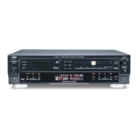
XL-R5000BK
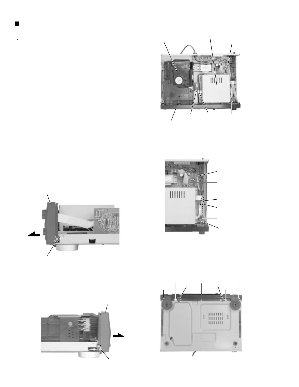
Prior to performing the following procedure, remove
the top cover.
Disconnect the card wires from connector CN501,
CN502, CN841, CN842 and CN861 on the main
board.
Remove the screw D attaching the microphone &
headphone board to the base chassis.
Remove the five screws E attaching the front panel
assembly at the bottom of the body.
Release the two joints a on both sides and the two
joints b on the bottom of the front panel assembly
using a screwdriver. Then remove the front panel
assembly toward the front.
1.
2.
3.
4.
Removing the front panel assembly
(See Fig.5 to 9)
Fig.5
Fig.6
Fig.7
Fig.8
Fig.9
Main board
CN861
Microphone &
headphone board
Joint a
(Bottom)
Joint a
D
D
E EE
CN841
CN842
Joint a
Front panel assembly
Joint a
Front panel assembly
CN861
CN502
CN501
Front panel assembly
CD-R mechanism cover
CD changer
mechanism assembly
www.freeservicemanuals.info
Digitized in Heiloo the Netherlands
 Loading...