XV-S300BK/XV-S332SL/XV-S402SL/XV-S403SG
8
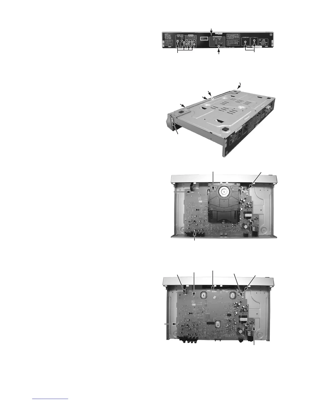
2.1.4 Removing the rear panel (see Fig.2-5)
• Prior to performing the following procedure, remove
the top cover.
(1) Remove the seven screws D attaching the rear panel
on the back of the body.
• As for the screw D, the number and the position are dif-
ferent according to the destination and model.
Fig.2-5
2.1.5 Removing the front panel assembly (see Fig.2-6,2-7)
• Prior to performing the following procedure, remove
the top cover.
• There is no need to remove the mechanism assembly.
(1) Remove the one screw E attaching the front panel
assembly on the bottom chassis.
(2) Disconnect the wire from CN702 and CN703 on the
main board respectively.
(3) Hook c and d are removed respectively, and the front
panel assembly is removed.
Fig.2-6
Fig.2-7
2.1.6 Removing the main board (see Fig.2-8)
• Prior to performing the following procedure, remove the top
cover, mechanism assembly and rear panel.
(1) Disconnect the wire from CN702 and CN703 on the
main board respectively.
(2) Remove the four screws F attaching the main board
on the bottom chassis.
Fig.2-8
D
D
D
Rear panel
E
Hook c
Hook d
Hook d
Front panel
assembly
CN702
CN703
Main board
Mechanism assembly
CN702
CN703
F
F
F
F
Main board
 Loading...