INSTALLATION GUIDE - REMOTE ACCESS CONTROLLER RAC 4 • PK3197_10_14
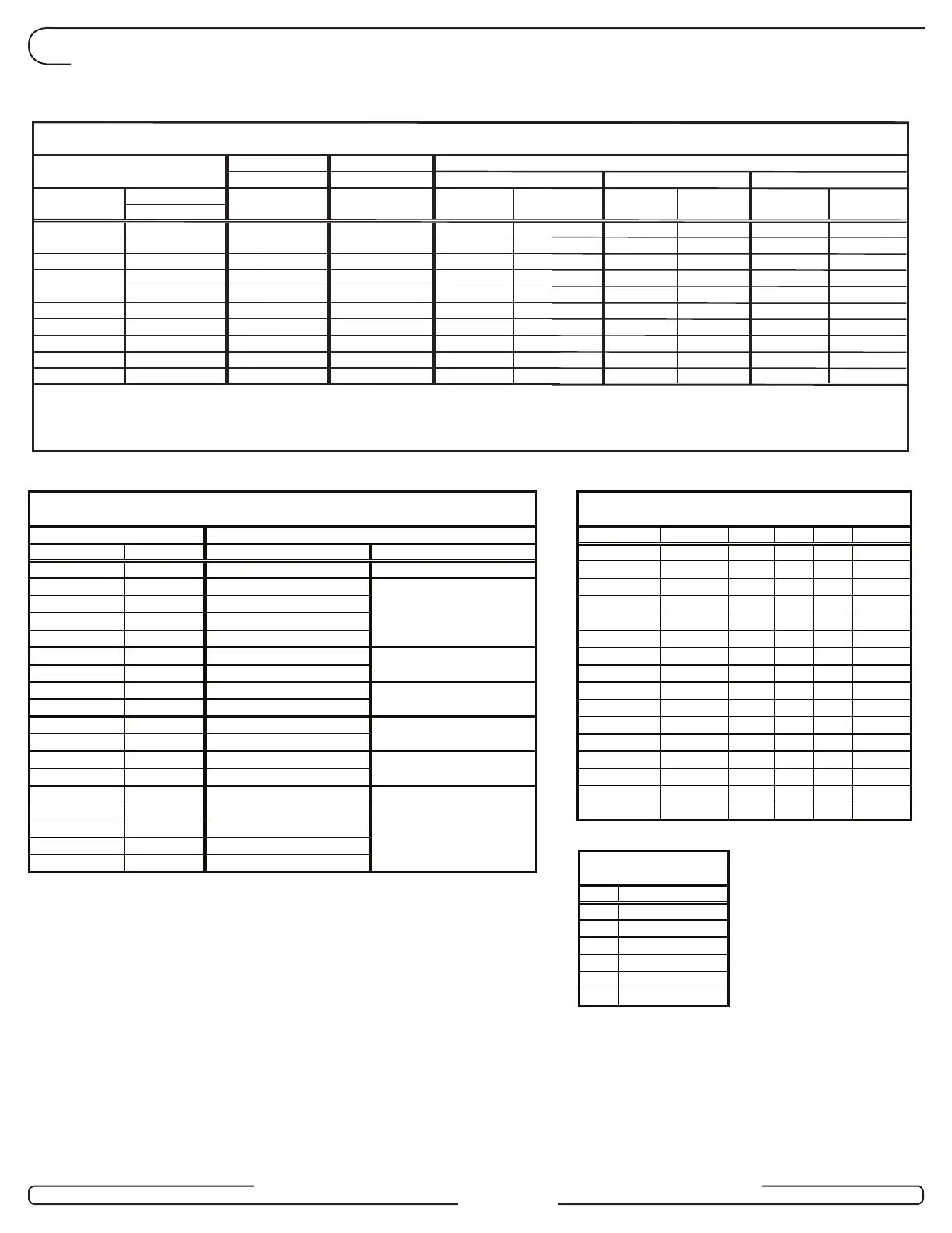
6.0 Annex A Wiring Diagram and Tables
Strike (H) or
Maglock (I)
TB1 pin 4
TB1 pin 3
-
RED
Power Adaptor (E) or (F)
Request to Exit (K)
BLACK
-
-
-
Table 3
-
-
Wire / Conn.
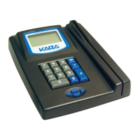
Remote Programming
Interface (L)
Controller Board - RAC 4 Peripherals Connections
Peripheral
Fire Alarm
BLACK
Description
Programming
Remote unlock (M)
-
-
J6 pin 1
J6 pin 2
J6 pin 3
J6 pin 4
-
-
BLACK
TB1 pin 1
TB1 pin 2
J19 pin 2
J19 pin 3
J16 pin 1
J16 pin 2
J18 pin 2
J18 pin 3
J18 pin 4
J19 pin 1
GND
COM
J8 pin 2
J8 pin 3
J8 pin 4
J18 pin 1
GND
REX
GND
12V LCK
NC
NO
12V
GND
GND
FIRE ALM
REM UNL
DB9
SignalPCB Conn.
J5
J8 pin 1
CGND
TX
RX
GND
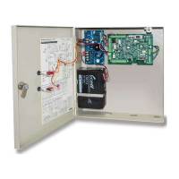
Controller Board
PCB Status LEDs
Access Delay (SW2 on PCB)
Functionality 1
Functionality 2
D42
D43
D46
Initialization
Programming
D44
D45
Access
Relay 0
Table 2
RE-INIT
LED
D41
Description
OFFOFF OFFOFF
90
ON OFFOFF OFF 120
OFFONOFF OFF
50
ON ON OFFOFF 60
OFFOFF ON OFF
35
ON OFFONOFF 40
OFFONONOFF
25
ON ON ON OFF30
OFFOFF OFFON
15
ON OFFOFF ON 20
OFFONOFF
1
3
ON
5
ON ON OF
0
OFF
ON
12
ON
ON
ON
ON
OFFON
Sec.
8
13
ON
4
ON OFFONON
3
ON
5
6
ON2
3
8
9
10
11
15
16
OFF
Table 4
CFG
4
7
12
14
1ON
(3)
Wire connection to back of contactless card reader.
J3 pin 3
J3 pin 4
Ingress
Swipe
J3 pin 1
J3 pin 2
Controller Board - RAC 4 Card Reader Connections
Controller Board
J1 pin 1
J2 pin 2
J2 pin 3
R71-6XXX
TB-2
TB-1
RED
(1)
Verify correct swipe reader model before connecting wires.
-
PURPLE
J2 pin 1
Wire Color
J1 pin 2
J1 pin 3
-
PURPLE / BLACK
WHITE TB-4
WHITE
-
TB-3WHITE / BLACK
YELLOW
YELLOW / BLACK
-
RED
--
GREEN
Red LED +
-
Green LED + -RED
-
-
RED / BLACK
Green LED -
Red LED - -YELLOW / BLACK
(2)
Contactless reader jumper wires must be installed as per wiring diagram:
J2 pin 1 to J3 pin 1 & J2 pin 2 to J3 pin 2 for Ingress
J12 pin 1 to J13 pin 1 & J12 pin 2 to J13 pin 2 for Egress.
-
-
-
RED / BLACK
YELLOW
Signal
Data +
Data -
Reader Config
Vcc (5V)
GND
12V
Term Block
BLACK
-
WHITE / BLACK
Insert
Contactless
PURPLE / BLACK
PURPLE
WHITE
R71-4XXX
Wire Color Wire Color
R79-1N1
-
-
TB-6
TB-7
RED
TB-4
WHITE
TB-3
-
GREEN
-
-
-
-
-
-
-
Term Block
BLACK
Wire Color
R79-1E1
-
-
(4)
TB-1 (BLACK)
TB-2 (RED)
TB-5 (YELLOW)
Factory Connected
-
-
-
-
-
-
J4-2
J4-1
J5-2
J5-1
Term Block
-
-
-
-
-
-
BLACK
RED
WHITE
GREEN
Wire Color
R79K-1XX-XX
Page 18