INSTALLATION GUIDE - REMOTE ACCESS CONTROLLER RAC 4 • PK3197_10_14
Page 6
3.1 Parts and Tools List
NOTE:
- Some items are dependant on the
options or configuration purchased.
Please ensure all parts ordered &
required for installation are available
before beginning.
- Parts are subject to change without
notice.
- For letter designations refer to Figure 9.
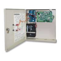
RAC 4 Enclosure:
NOTE: All items above come factory
installed.
(A) RAC 4 enclosure with access door
(B) Controller PCB
(C) Cam-lock
(D) DC power jack
Cables (not shown):
NOTE: Some items come factory
installed.
(E) System cables:
- Controller PCB to adaptor jack
- Controller PCB jumpers (card
reader type dependent)
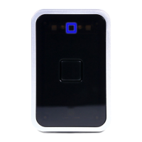
Card Reader(s):
NOTE: Type of card reader(s) dependent
on system configuration ordered.
(F) Swipe reader (see Figure 4)
(F) Insert reader (see Figure 6) – may
require additional tools as per PK3166
included with the reader.
(F) Contactless reader (see Figure 7)
Locking Device
NOTE: Locking device(s) dependent on
system configuration ordered.
(G) Electric strike
(H) Electromagnetic Lock
Power Adaptor includes:
NOTE: Dependent on country’s electrical
power requirements.
(I) 1x North America 12 VDC output power
adaptor with integrated 6 foot (1.8 m)
power cable. Input power requirements
of 110-120 VAC, 60 Hz.
or
(J) 1x International 12 VDC output power
adaptor with integrated 6 foot (1.8
m) power cable and interchangeable
AC outlet prongs. Input power
requirements of 220-240 VAC, 50-60
Hz.
Other Peripherals (optional):
(K) Request to Exit button
(L) Remote Programming Interface (RPI)
(M) Remote Unlock (Not shown)
Programming Device
NOTE: Purchased separately, dependent
on hotel configuration.
IMPORTANT:
Programming of the RAC 4 can only
be done with the following versions of
programming device software:
- ATLAS: software version 1.0 or higher
- Kaba Ilco 780 FDU: software version
6.40 or higher
- Kaba Ilco FDU 4 (G4): all versions
(N) Front Desk Unit (FDU)
(N) ATLAS with Infra-red Programming
Module (IPM)
Installation Hardware Bag:
(O) 4x Philips wood screw #8 x 1-1/4"
(P) 4x Nylon anchor #6 – 10
(Q) 4x Concrete anchor #7 – 9
(R) 1x Strain relief connector with locking
nut
(S) 1x Strain relief bushing
(T) 2x Diode-rectifier
(U) 5x steel flat washer #8
(V) 3x Crimp terminal B connector
Mandatory tools required:
• Safety glasses
• Electric drill
• 9/64" (3.5 mm) drill bit
• 7/32" (5.6mm) drill bit
• 1/4" (6.5 mm) drill bit
• 3/8" (9.5 mm) drill bit
• Philips screwdriver (#2)
• Slotted screwdriver tip width 3/32"
• Adjustable wrenches
• Crimp tool (18-22 AWG)
• Pliers
• Wire cutter / stripper
• FDU/ATLAS programmed "Test lock"
Keycard
• Hammer or rubber mallet
• Awl or center punch
3.0 Checklist and Exploded Views