INSTALLATION GUIDE - REMOTE ACCESS CONTROLLER RAC 4 • PK3197_10_14
Page 22
6.0 Annex B Peripheral Wiring Diagrams
REX
EXIT
The Remote Unlock input (J8, pins 1 & 2) unlocks the door only for the
delay set by the DIP switches, EVEN if the button stays pressed.
The REX input (J8, pins 3 & 4) unlocks the door for as long as the button
is pressed PLUS the delay set by the DIP switches.
The Exit Button can be connected to either the Remote Unlock or the REX
input, depending on the required functionality. In both cases, the wires
should be connected to the Normally Open contact of the Exit button.
In general, a Motion Detector or a maual override should be connected to
the REX input (J8, pins 3 & 4).
NO COM NC
Remote
Unlock
EXIT
NO COM NC
RAC 4 PCB
5V
NO
5V GND 12V 1 2 3 1 2 3 4
NC COM GND FIRE GND COMNCNO12VGNDLBATACFGND12V
GND
J1
J16 J18 J19
J2 J3
12V 1 2 3
1 2 31
1 23 41 21 2 3
2 3
1 2 3 4
1 2 3 4
GNDDOORGNDTPRGNDREXGNDREM CGNDTXRXGND
J8 J6
1 2 3 4 1 2 3 4
Black Wire
Red Wire
Motion
Detector
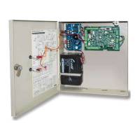
RAC 4 Enclosure
CNO NC
12V
+ -
RAC 4 PCB
5V
NO
5V GND 12V 1 2 3 1 2 3 4
NC COM GND FIRE GND COMNCNO12VGNDLBATACFGND12V
GND
J1
J16 J18 J19
J2 J3
12V 1 2 3
1 2 31
1 23 41 21 2 3
2 3
1 2 3 4
1 2 3 4
GNDDOORGNDTPRGNDREXGNDREM CGNDTXRXGND
J8 J6
1 2 3 4 1 2 3 4
Figure 9: Motion Detector Wiring
Figure 8: Request to Exit (REX) or Remote Unlock Button Wiring