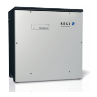
3 Description of the device
3.1 Mode of operation
An external EMS/PMS
2
is required to operate the device. The EMS/PMS must be provided by the customer/
system integrator. Modbus TCP is the sole means of communication with the device.
The necessary commands and data points are described in the SunSpec Protocol description [See sec-
tion1.1}Page4].
The shutdown threshold (DC-Min.) is dynamically determined by the device on the basis of the current grid
voltage. After shutting down the device, it is therefore not possible to guarantee reconnection as there may be
a change in the grid voltage.
3.2 Device diagram
Fig.3: Device diagram
Key
1 Housing 5 AC connection / cable feed-through
2 Cover 6 Interface / cable feed-through
3 Status indicator 7 Communication - button / USB port
4 Upper cover 8 DC connection / cable feed-through
3.2.1 Electrical functions
A potential-free relay contact is integrated into the device. Use this contact for one of the following functions:
Potential-free relay
The potential-free relay contact closes as soon as there is a fault during operation. You use this function, for ex-
ample, to signal a fault visually or acoustically.
3.2.2 Interfaces
You can configure the interfaces and the web server in the Settings menu. The device has the following inter-
faces for communication and remote monitoring.
Ethernet interface
Communication with the EMS/PMS is carried out via the Ethernet interface.
The local web server can be used to configure the device and perform updates.
2
Energy management system/power management system
Manual Description of the device | 3
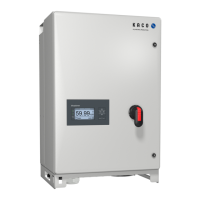
KACO blueplanet gridsave 92.0 TL3
Page 9
EN
 Loading...


