KPC-9612 Version 5.2 July 19, 1994
58
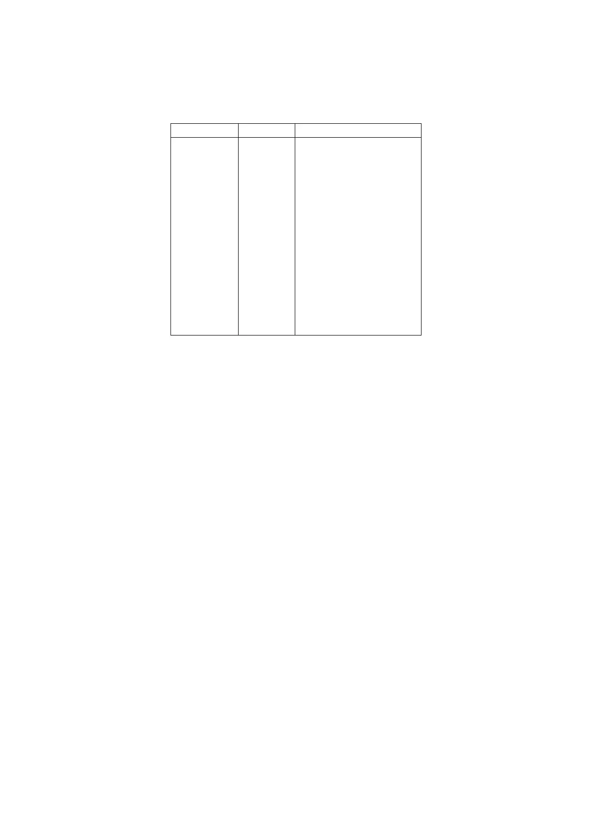
9600 Baud
The 9600 baud radio connector on the KPC-9612 rear panel is a 15-pin DB style connector. The pin
layout is shown on the FCC label on the bottom of the unit and the purpose of each pin is:
PTT
RXA
TXA
RXD
TXD
CTLA
CTLB
RX S/N
GND
GND
GND
RXC
XCD
N/C
N/C
Push-to-Talk
Receive signal
Transmit signal
Receive signal (digital)
Transmit signal (digital)
Control line A
Control line B
Receive quality
Ground
Ground
Ground
Receive clock
External carrier detect
No connection
No connection
Pin 1 When the KPC-9612 needs to key your transmitter, it will apply a ground to this pin. This is
an open-drain circuit and requires a positive voltage from your radio (not to exceed 50 Volts
and 200 mA).
Pin 2 This pin connects to the discriminator output from your radio (9600 baud receive data).
Pin 3 This pin connects to the modulator (normally to the varactor) of your radio for transmitting
9600 baud packet.
Pin 4 This pin can be used to receive 9600 baud data from those radios that provide TTL level
voltages for receive (such as the Kantronies D4-10 radio). This pin would normally only be
used to operate 19,200 baud packet. Normally, this pin will not be used.
Pin 5 This pin can be used for transmit data for those radios that accept TTL level transmit sig-
nals (such as the Kantronies D4-10 radio). This pin would normally only be used to operate
19,200 baud packet.
Pin 6 This pin is the CONTROL A output from the KPC-9612 which may be used as a control line
to your radio or other devices. It is an open-drain circuit, and will apply a ground on this
pin when controlled by the CTRL command in your KPC-9612 (not to exceed 50 volts and
200 mA).
Pin 7 This pin is the CONTROL B output from the KPC-9612 which may be used as a control line
to your radio or other devices. It is an open-drain circuit, and will apply a ground on this
pin when controlled by the CTRL command in your KPC-9612 (not to exceed 50 volts and
200 mA).
Pin 8 This line is used to adjust the receive equalization of the 9600 baud modem in the KPC-
9612. Connect a dc voltmeter to this pin and adjust R-33 for maximum reading while you
are receiving another station. (Note: J8 must be on the center post and 2 for this adjust-
ment.)