6
Electric Dispenser Hoist EWL 2, 3, 4
A 5 Mounting and connection
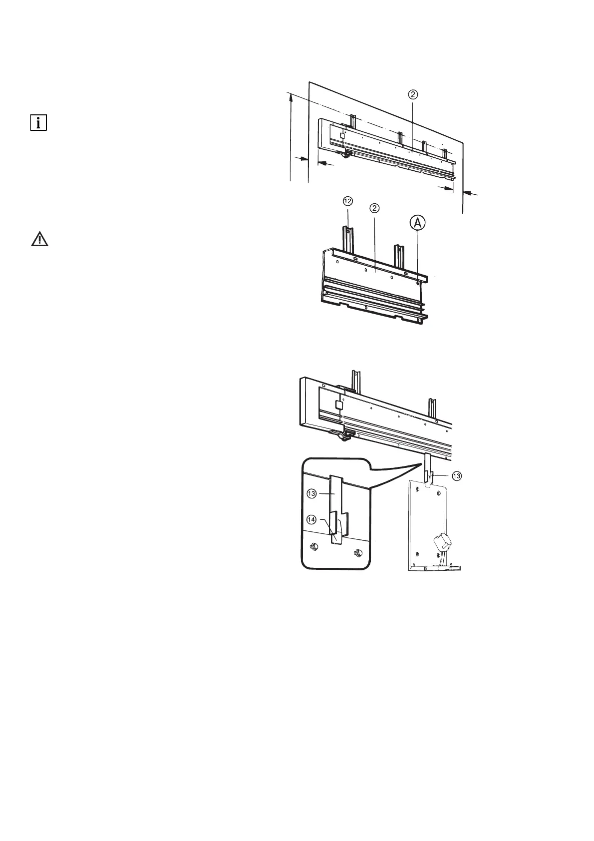
A 5.1 Mounting the guide rail
see A 12 Dimension sheet for silo
lift.
Mark the top installation level
(= 2560 mm) on the wall.
Hold the guide rail 2 with its top holes w
against this line and mark the holes.
Please observe the lateral mini-mum
wall distances (right 150 mm, left
100 mm)!
Centre drill the marked holes
∅ 10 x 90 mm and insert dowel plugs.
Screw on the guide rail ” except for
screw (A) and align it horizon-tally.
A 5.2 Later mounting of the guide
rail with EWL Plaster Dispenser 30
already fitted
Fit the mounting strip e in the top guide
bracket r of the dis-penser console.
Apply the guide rail 2 horizontally and
insert the groove t in the mounting strip.
Align the guide rail 2 horizontally and
fasten it to the wall (see 5.1).