3-10 COOLING SYSTEM
Water Pump
Water Pump Removal
0 Remove:
Muffler (see Muffler Assembly Removal)
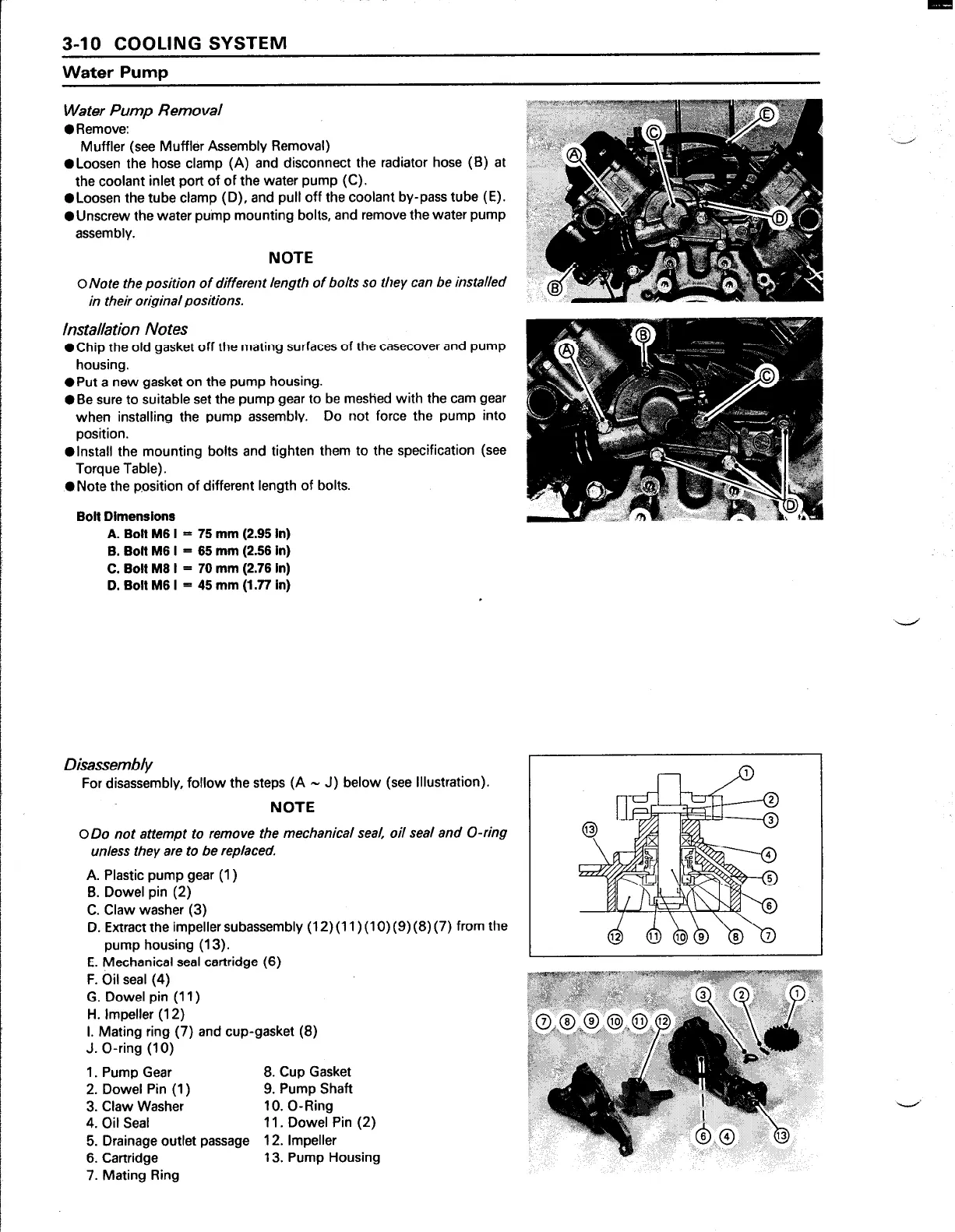
0 Loosen the hose clamp (A) and disconnect the radiator hose (B) at
the coolant inlet port of of the water pump (C).
l
Loosen the tube clamp (D), and pull off the coolant by-pass tube (E).
@Unscrew the water pump mounting bolts, and remove the water pump
assembly.
NOTE
0
Note the position of different length of bolts so they can be installed
in their original positions.
Installation Notes
@Chip the old gasket off the mating surfaces of the casecover and pump
housing.
l
Put a new gasket on the pump housing.
l
Be sure to suitable set the pump gear to be meshed with the cam gear
when installing the pump assembly.
Do not force the pump into
position.
@Install the mounting bolts and tighten them to the specification (see
Torque Table).
0 Note the p.osition of different length of bolts.
Boll Dimensions
A. Bolt M6 I = 75 mm (2.95 in)
B. Bolt M6 I = 65 mm (2.56 in)
C. Bolt M6 I = 70 mm (2.76 In)
D. Bolt M6 I = 45 mm (1.77 in)
Disassembly
For disassembly, follow the steps (A - J) below (see Illustration).
NOTE
0
Do not
attempt
to remove the mechanical seal, oil seal and O-ring
unless they are to be replaced.
A. Plastic pump gear (1)
B. Dowel pin (2)
C. Claw washer (3)
D. Extract the impeller subassembly (12)(11)(10)(9)(8)(7) from the
pump housing (13).
E. Mechanical seal cartridge (6)
F. Oil seal (4)
G. Dowel pin (11)
H. Impeller (12)
I. Mating ring (7) and cup-gasket (8)
J. O-ring (10)
1. Pump Gear
8. Cup Gasket
2. Dowel Pin (1)
9. Pump Shaft
3. Claw Washer
10. O-Ring
4. Oil Seal
11. Dowel Pin (2)
5. Drainage outlet passage 12. Impeller
6. Cartridge
13. Pump Housing
7. Mating Ring
I



 To Next Page