“The Right Control for Your Application.”
12095 NW 39 Street, Coral Springs, FL 33065-2516
KB Electronics, Inc. Phone: 954-346-4900; Fax: 954-346-3377
(A40288) - Rev. E - 6/6/2005 - Z3562E00 Page 7 of 20
Table 2
General Performance Specifications
Description Specification Factory Setting
115 Volt AC Line Input Voltage Operating Range (Volts AC) 115 (±15%) —
208/230 Volt AC Line Input Voltage Operating Range (Volts AC) 208 (-15%) / 230 (+15%) —
Maximum Load (% Current Overload for 2 Minutes) 150 —
Carrier, Switching Frequency (kHz) 16, 8 —
Signal Following Input Voltage Range
1
(Volts DC)
0 - 5 —
Output Frequency Resolution (Bits, Hz) 10, .06 —
Minimum Speed Trimpot (MIN) Range (% Frequency Setting) 0 - 40 0
Maximum Speed Trimpot (MAX) Range (% Frequency Setting) 70 - 110 100
Acceleration Trimpot (ACC) and Deceleration Trimpot (DEC/B) Range (Seconds) .3 - 20 1.5
Boost Trimpot (DEC/B) Range (50 Hz Only) (Volts/Hz) 0 - 30 5
Slip Compensation Trimpot (COMP) Range at Drive Rating (Volts/Hz) 0 - 3 1.5
KBVF-21D .65 - 1.8 1.6
KBVF-22D 1.0 - 2.8 2.4
KBVF-13, 23, 23D 1.5 - 4.5 3.8
KBVF-14, 24, 24D 2.5 - 7.5 6.4
Current Limit Trimpot (CL) Range (Amps AC)
KBVF-26D 3.5 - 10.5 8.8
Motor Frequency Setting (Hz) (Jumper J1) 50, 60 60
Output Frequency Multiplier (X1, X2) (Jumper J2)
2
1, 2 1
Minimum Operating Frequency at Motor (Hz) 1 —
Speed Range (Ratio) 60:1 —
Speed Regulation (30:1 Speed Range, 0 - Full Load) (% Base Speed)
3
2.5 —
Overload Protector Trip Time for Stalled Motor (Seconds) 6 —
AC Line Input Undervoltage/Overvoltage Trip Points for 115 Volt AC Line (±5%) (Volts AC)
4
76 - 141 —
AC Line Input Undervoltage/Overvoltage Trip Points for 208/230 Volt AC Line (±5%) (Volts AC)
4
151 - 282 —
Operating Temperature Range (°C) 0 - 45 —
Notes: 1. If a non-isolated signal is used, install the SIVFR - Signal Isolator (Part No. 9597). 2. Allows the motor to operate up to two times the rated RPM.
Constant horsepower will result when operating the drive in the "X2" mode. 3. Dependent on motor performance. 4. Do not operate the drive outside the specified
AC line input voltage operating range.
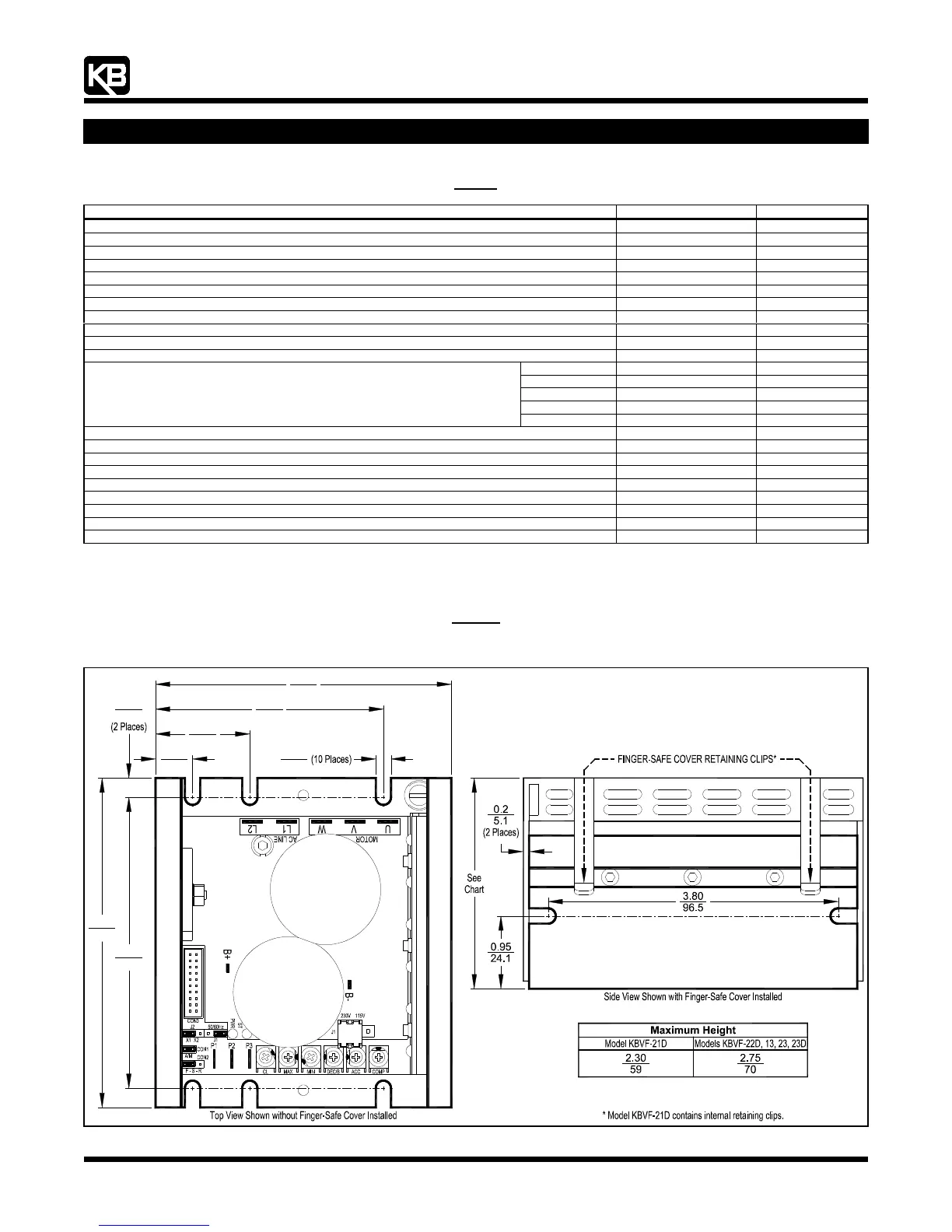
Figure 2
Models KBVF-21D, 22D, 13, 23, 23D Mechanical Specifications and Control Layout (Inches/mm)
(Model KBVF-22D Shown)
(See Figure 4, On Page XX, for Expanded View of Jumpers and Trimpots)
109
96.5
3.80
31.8
1.25
4.30
12.7
0.5
0.25
6.4
5.1
0.2
76.2
3.00
3.90
99.0