14
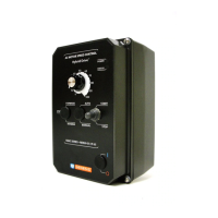
Model KBAC-29: Designed to accept single-phase (Terminals “L1”, “L2”) or 3-phase (Terminals “L1”,
“L2”, “L3”) AC line input. Rated for 208/230 Volt AC line input only. See Figure 8.
Models KBAC-45, 48: Designed to accept 3-phase (Terminals “L1”, “L2”, “L3”) AC line input only.
Rated for 400/460 Volt AC line input only. See Figure 8.
5.2 GROUND CONNECTION – Connect the ground wire (earth) to the Green Ground Screw. The Ground
Screw is located next to Terminal Block TB1. See Figure 7, on page 13, and Figure 8.
5.3 MOTOR CONNECTION – Wire the motor to Terminal Block TB1 Terminals “U”, “V”, “W”. See Figure
7, on page 13, and Figure 8. Motor cable length should not exceed 100 ft (30 m) – special reactors
may be required – consult our Sales Department.
Be sure Jumper J2 is set to the corresponding motor horsepower rating, as described in Section 6.2,
on page 17.
5.4 REMOTE MAIN SPEED POTENTIOMETER
CONNECTION – The drive is supplied with a
prewired Main Speed Potentiometer mounted
on the front cover.
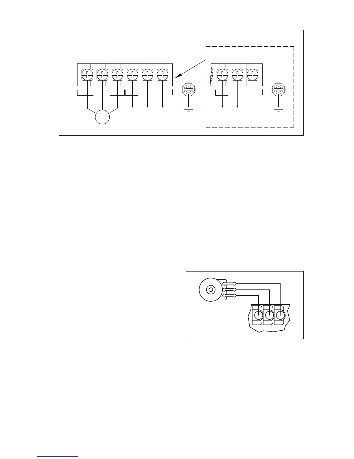
To operate the drive from a remote poten-
tiometer (5 kΩ), remove the white, orange,
and violet potentiometer leads from Terminals
“P1”, “P2”, and “P3”. The wires may be taped
and left inside the drive. The potentiometer
assembly may be removed if a watertight seal
is used to cover the hole in the front cover.
Wire the Main Speed Potentiometer to
Terminals “P1” (low side), “P2” (wiper), and “P3” (high side). See Figure 9.
WARNING! Do not earth ground any Main Speed Potentiometer terminals.
Application Note – If it is required that the Remote Main Speed Potentiometer be isolated from the
AC line, install the SIAC Signal Isolator (Part No. 9600).
5.5 REMOTE START/STOP SWITCH CONNECTION – The drive is supplied with a prewired Start/Stop
Switch mounted on the front cover to electronically start and stop the drive.
To operate the drive from a remote Start/Stop Switch (type (ON)-OFF-ON, SPDT), remove the white,
black, and red wires from Terminals “RUN”, “COM”, and “STOP”. The wires may be taped and left
FIGURE 8 – MODELS KBAC-29*, 45, 48 AC LINE INPUT, MOTOR, AND GROUND CONNECTIONS
 Loading...