16
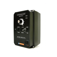
The Enable function is established by
wiring a switch or contact in series with
the orange Main Speed Potentiometer
lead which connects to Terminal “P2”.
When the Enable Switch is closed, the
motor will accelerate to the Main
Speed Potentiometer setting. When
the Enable Switch is opened, the
motor will decelerate to stop.
WARNING! If the Enable
Switch is to be mounted
remotely, it is highly recommended
that the SIAC Signal Isolator
(Part No. 9600) be installed.
5.9 Run/Fault Relay Connection – The Run/Fault
Relay Output Contacts are located at TB2 and
can be used to turn on or off equipment or to
signal a warning if the drive is put into the Stop
Mode or a fault has occurred. See Figure 15.
The Run/Fault Relay Contact status for various
drive operating conditions is shown in Table 6.
FIGURE 14 – ENABLE CIRCUIT CONNECTION
6 SETTING SELECTABLE JUMPERS
The drive has customer selectable
jumpers which must be set before
the drive can be used. For the
location of jumpers, see Figure 2,
on page 9.
Note: Disconnect the AC line
before changing position of
jumpers.
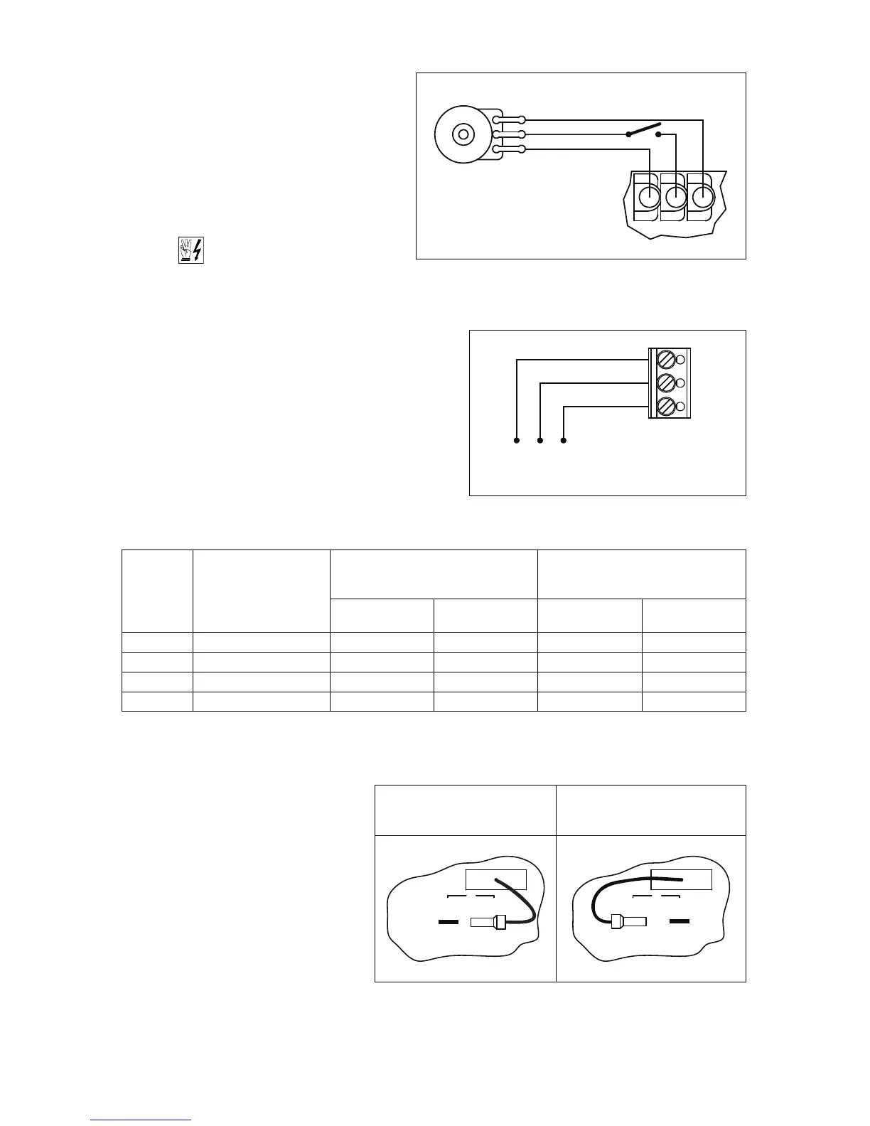
6.1 LINE INPUT VOLTAGE
SELECTION (J1 (MODELS
KBAC-24D, 27D ONLY)) –
Jumper J1 is factory installed
on Terminal “230V” for 208/230 Volt AC line input. For 115 Volt AC line input, the jumper must be
removed and installed on Terminal “115V”. See Figure 16.
Drive
Operating
Condition Description
Run Relay Operation
(Jumper J8 Installed in “R” Position)
(Factory Setting)
Fault Relay Operation
(Jumper J8 Installed in “F” Position)
Normally
Open Contact
Normally
Closed Contact
Normally
Open Contact
Normally
Closed Contact
Power Off Main Power Disconnected Open Closed Open Closed
Run Mode* Normal Drive Operation Closed Open Closed Open
Stop Mode* Selected by Operator Open Closed Closed Open
Fault** Drive Tripped Open Closed Open Closed
TABLE 6 – DRIVE OPERATING CONDITION AND RUN/FAULT RELAY CONTACT STATUS
*Run Mode or Stop Mode is selected using the Start/Stop Switch. **Overload, I
2
t, Short Circuit, Undervoltage, Overvoltage.
FIGURE 16 – MODELS KBAC-24D*, 27D AC LINE INPUT VOLTAGE SELECTION
208/230 Volt AC Line Input
(Factory Setting)
(J1 Installed on Terminal “230V”)
115 Volt AC Line Input
(J1 Installed on Terminal “115V”)
 Loading...