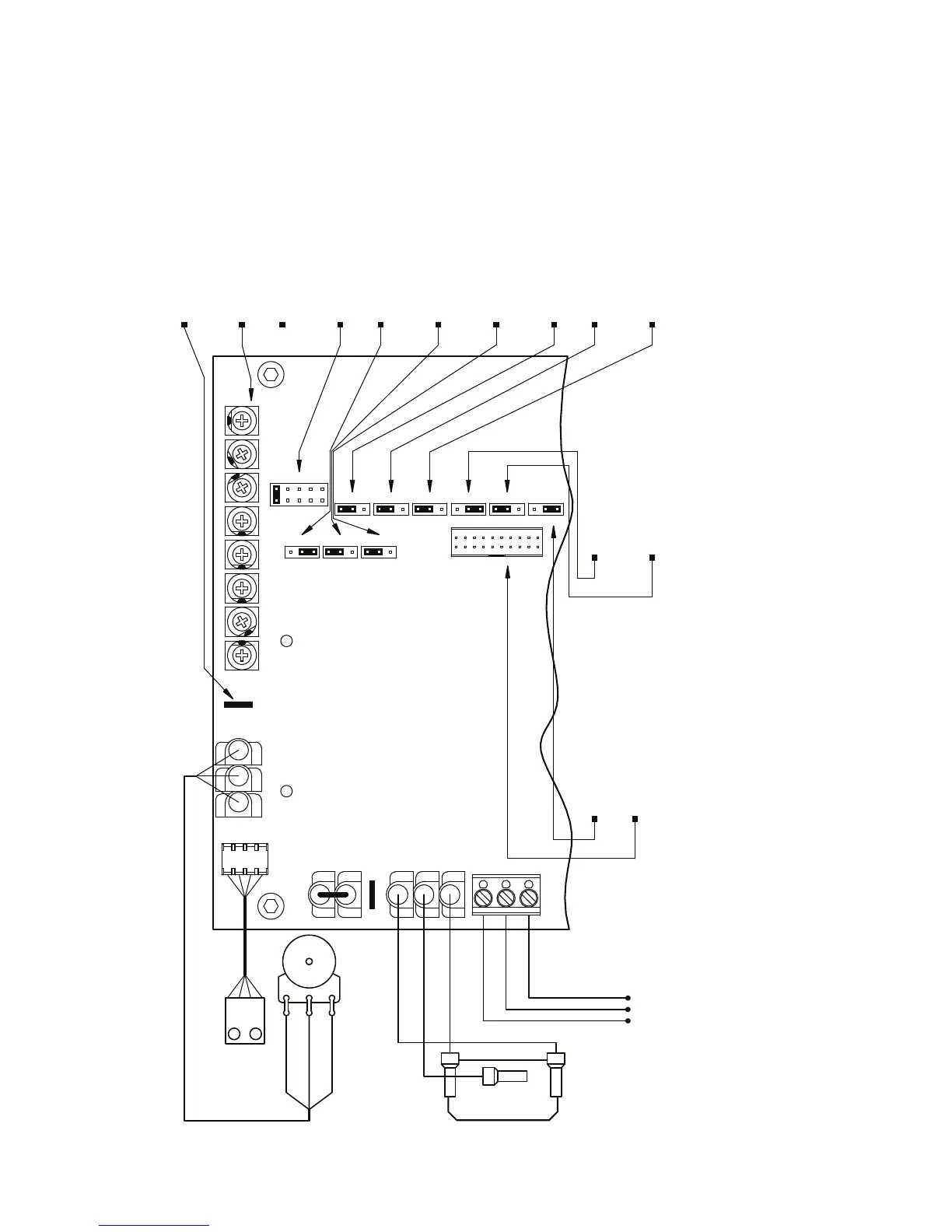
Output Contacts:
Run/Fault Relay
Start/Stop Switch:
Main Speed Potentiometer:
Diagnostic LEDs:
J4: 1X or up to 2X
J9: Normally Open or ClosedJ11: I t Overload selection.
CON1: Used to connect
optional accessories to the drive.
Stop Contact selection.
Torque selection.
J10: Constant or Variable
J7: Regenerative or
Output Relay Operation selection.
Injection Braking selection.
J8: "Run" or "Fault"
J6: Fixed or Adjustable Boost selection.
Rated Motor RPM Operation selection.
Motor Operation selection.
J5: 60 Hz or 50 Hz
All jumpers and trimpots are shown in factory set positions.
J1: AC Line Input Voltage selection
J2: Motor Horsepower selection
3
.
(Models KBAC-24D, 27D only).
J3: Automatic Ride-Through
4
or Manual Start selection.
Used with optional Run-Stop-Jog Switch Kit.
Adjustable Trimpots
2
.
JOG Terminal.
See Section 6.6, on page 18.
See Section 6.7, on page 18.
See Section 6.4, on page 17.
See Section 6.4, on page 17.
See Section 6.5, on page 18.
See Section 6.1, on pages 16 – 17.
See Section 6.2, on page 17.
See Section 6.3, on page 17.
See Section 12, on pages 22 – 25.
See Table 2, on page 8.
2
see Section 5.5,
see Section 5.9,
on page 16.
on pages 14 – 15.
Normally Closed
Red
Normally Open
Relay Common
see Section 5.4, on page 14.
Black
White
See Section 6.10, on page 18.
See Table 2, on page 8.
See Section 6.8, on page 18.
See Section 6.9, on page 18.
White (Low) (P1)
Violet (High) (P3)
Orange (Wiper) (P2)
see Section 11, on pages 21 – 22.
STATUS
POWER
STOP
NCNO COM
FWDCOM RUN REV COM
CON2
JOGP1P3 P2
ACCELMINMAX JOGCLDECEL BOOST
TB2
MA
J3
2X
J4
50Hz
J5
60Hz 1X
J8J9
NCNO F
J11 J10
CT21 VT
CON1
FIX
J6
RGR INJ
J7
ADJ
A
J2
E
C
D
B
COMP
9
FIGURE 2 – CONTROL LAYOUT
1
Notes: 1. Layout of Model KBAC-24D varies slightly. 2. On Model KBAC-24D, the JOG and COMP Trimpots are located vertically, along the right edge of the PC board (below the mounting screw). 3. On Model KBAC-24D, Jumper J2 is
labeled “1”, “3/4”, “1/2”, “1/4”, “1/8” (factory set to the “1” position). On Model KBAC-27D, Jumper J2 is labeled “2”, “1
1
⁄2”, “1”, “3/4”, “1/2” (factory set to the “1
1
⁄2” position). On Models KBAC-29, 45, 48, Jumper J2 is labeled “A”, “B”,
“C”, “D”, “E” (factory set according to Table 4, on page 10. 4. On Model KBAC-24D, Jumper J3 is labeled “AUTO” and “MAN”.
 Loading...