inside the drive. The switch assembly may be
removed if a liquidtight seal is used to cover
the hole in the front cover. After applying
power to the drive, momentarily set the
Start/Stop switch to the “START” position.
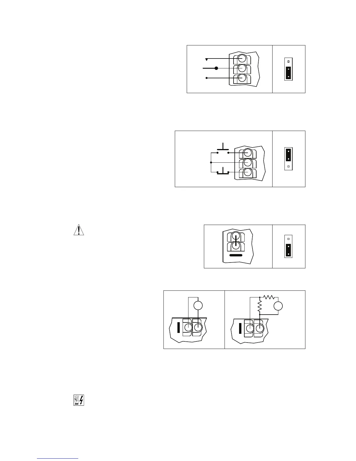
For Start/Stop Switch with normally open stop
contact, set Jumper J9 to the “NO” position
(factory setting). For Start/Stop Switch with
normally closed stop contact, set Jumper J9
to the “NC” position. See Figures 10 and 11.
Also see Section 6.8, on page 18.
5.6 AUTOMATIC RESTART – Automatic
restart requires the elimination of the
Start/Stop Switch. Remove the white,
black, and red wires from Terminals
“RUN”, “COM”, and “STOP”. The wires
may be taped and left inside the drive.
The switch assembly may be removed if
a liquidtight seal is used to cover the hole
in the front cover.
To eliminate the start/stop function, hard-
wire Terminals ”RUN” and “COM” with the jumper
that is provided. Be sure Jumper J9 is set to the
“NO” position. See Figure 12.
WARNING! Using a jumper to eliminate the
start/stop function will cause the motor to
run at the Main Speed Potentiometer setting when
the AC line is applied.
5.7 VOLTAGE FOLLOWING CONNECTION – An isolat-
ed* 0 – 5 Volt DC analog signal input can also be
used to control motor speed in lieu
of the Main Speed Potentiometer.
The drive output will linearly follow
the analog signal input. Wire the sig-
nal input positive lead (+) to Terminal
“P2” and the negative lead (-) to
Terminal “P1”. With external circuitry,
a 0 – 10 Volt DC analog signal can
also be used. See Figure 13.
*If a non-isolated signal is used,
install the SIAC Signal Isolator (Part No. 9600). The SIAC accepts voltage (0 to ±2.5 thru 0 to ±25
Volts DC) or current (4 – 20 mA DC) signal inputs. See Table 2, on page 8.
Note: For signal following operation, the Minimum Speed Trimpot (MIN) must be set fully counter-
clockwise.
WARNING! The signal input must be isolated from the AC line. Earth grounding signal
wiring will damage the drive and void the warranty. It is highly recommended that the
SIAC Signal Isolator (Part No. 9600) be installed when using signal following.
5.8 ENABLE CIRCUIT CONNECTION – The drive can also be started and stopped with an Enable circuit
(close to run, open to stop). See Figure 14, on page 16.
15
FIGURE 10 – REMOTE START/STOP SWITCH CONNECTION
WITH NORMALLY OPEN STOP CONTACT
(J9 Installed in “NO” Position)
 Loading...