WARNING! To avoid motor winding overheating and failure,
do not overboost the motor.
Note: An unloaded motor with excessive boost will draw more
current than a partially loaded motor.
The boost voltage may be adjusted as follows:
1. Wire an AC RMS ammeter in series with one motor phase.
2. Run the motor unloaded at approximately 4 Hz (or 120 RPM).
3. Increase the boost until the ammeter reaches the motor
nameplate rated current (Amps AC).
4. Using the Main Speed Potentiometer, slowly adjust the motor speed over a 1 – 15 Hz (0 – 450
RPM) range. If the motor current exceeds the nameplate rating, decrease the boost setting.
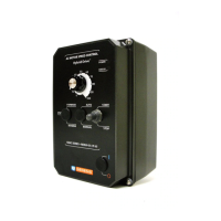
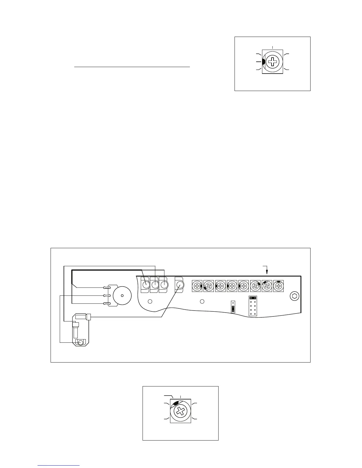
12.9 JOG (JOG) – The Jog feature requires the installation of a Run-Stop-Jog Switch. The switch must be
wired according to Figure 39. The JOG Trimpot range is shown in Figure 40.
The orange Main Speed Potentiometer wire (wiper) which connects to Terminal “P2” on the drive must
be removed and installed on Terminal “RUN” on the switch. The “JOG” Terminal on the drive connects
to “JOG” on the switch. Terminal “P2” on the drive connects to the center (common) terminal on the
switch.
When the switch is in the “JOG” position, the JOG Trimpot is used to set the “jog” speed. When the
switch is in the “RUN” position, the Main Speed Potentiometer is used for speed setting.
The Run-Stop-Jog Switch (Part No. 9340) is available as an optional accessory. See Table 2,
on page 8.
25
 Loading...