8
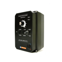
Description
1
PC Board
Designation
KBAC-24D KBAC-27D KBAC-29 KBAC-45 KBAC-48
AC Line Input Voltage (115, 230) J1
3 3
— — —
Motor Horsepower (see Table 4 - Electrical Ratings, on page 10) J2
3 3 3 3 3
Automatic Ride-Through or Manual Restart (A*, M) J3
3 3 3 3 3
Frequency Multiplier (1X, 2X) J4
3 3 3 3 3
Motor Frequency (50Hz, 60Hz) J5
3 3 3 3 3
Fixed or Adjustable Boost (FIX, ADJ) J6
3 3 3 3 3
Regenerative or DC Injection Braking (RG, INJ) J7
3 3 3 3 3
“Run” or “Fault” Output Relay Operation (R, F) J8
3 3 3 3 3
Normally Open or Closed Stop Contact (NO, NC) J9
3 3 3 3 3
Constant or Variable Torque (VT, CT) J10
3 3 3 3 3
I
2
t Overload Selection (1, 2)
J11
3 3 3 3 3
TABLE 1 – JUMPER SELECTABLE FEATURES
TABLE 2 – OPTIONAL ACCESSORIES
Notes: 1. Bold indicates factory setting. 2. In Automatic Ride-Through Mode, the drive will automatically restart due to a momentary power loss of less
than 2 seconds.
Notes: 1. Complies with CE Council Directive 89/336/EEC Industrial Standard. 2. If a USB communication cable is required, purchase Part No. 19008.
3. Other protocols available – contact our Sales Department.
Description
Model
KBAC-24D
Model
KBAC-27D
Model
KBAC-29
Model
KBAC-45
Model
KBAC-48
Forward-Stop-Reverse Switch – Provides motor reversing and stop functions.
Mounts on the enclosure cover and is supplied with a switch seal to maintain
liquidtight integrity.
9480 9480 9480 9480 9480
On/Off AC Line Switch – Disconnects the AC line. Mounts on the enclosure
cover and is supplied with a switch seal to maintain liquidtight integrity.
9482 9523 9532 9532 9532
Run-Stop-Jog Switch – Selects speed setting from either the Main Speed
Potentiometer or the JOG Trimpot. Mounts on the enclosure cover and is supplied
with a switch seal to maintain liquidtight integrity.
9340 9340 9340 9340 9340
Signal Isolator – Provides isolation between a non-isolated signal source and the
drive. Mounts on the drive’s PC board with four snap-ins.
9600* 9600* 9600* 9600* 9600*
Auto/Manual Switch – When used with the Signal Isolator, it selects remote
process signal or the Main Speed Potentiometer. Mounts on the enclosure cover
and is supplied with a switch seal to maintain liquidtight integrity.
9481 9481 9481 9481 9481
AC Line Filter
1
– Provides Class A RFI (EMI) suppression.
Installs onto the drive’s PC board with quick-connect terminals.
Suffix “S”: Filter is used when On/Off AC Line Switch is installed.
Suffix “NS”: Filter is used when On/Off AC Line Switch is not installed.
Suffix “S” 9516 9512 9479 9479 9479
Suffix “NS” 9507 9512 9515 9515 9515
Multi-Speed Board – Provides multi-speed operation using external contacts or a
PLC. Mounts on the drive’s PC board with four snap-ins.
9489 9489 9489 — —
Programming Kit
2
– Includes DownLoad Module™ (DLM) handheld programming
device which uploads and downloads drive programs, PC to DLM serial communica-
tion cable, DLM to drive communication cable, and PC Windows® based Drive-
Link™ communication software.
9582 9582 9582 9582 9582
Modbus Communication Module – Allows direct communication between drive
and Modbus
3
protocol.
9517 9517 9517 9517 9517
Liquidtight Fittings – Provide a liquidtight seal for wiring the drive. Kit includes
three 1/2” and one 3/4” liquidtight fittings
9526 9526 9526 9526 9526
* Warning! It is highly recommended that the Signal Isolator (Part No. 9600) be installed when using the
drive with external control signals.
 Loading...