V7.00
24449_EDEKZA0031-2619-1_DE-EN
7
F2
F1
+
52
Stromflußrichtung / current direction
L3
N
L2
L1
F3 F4
10
L1
13
N
-
51
21
l1
20
k1
41
K1
40
C
42
K2
2
N
43
K3
1
L
B
92
A
9091
K4 K5
44 45
3130
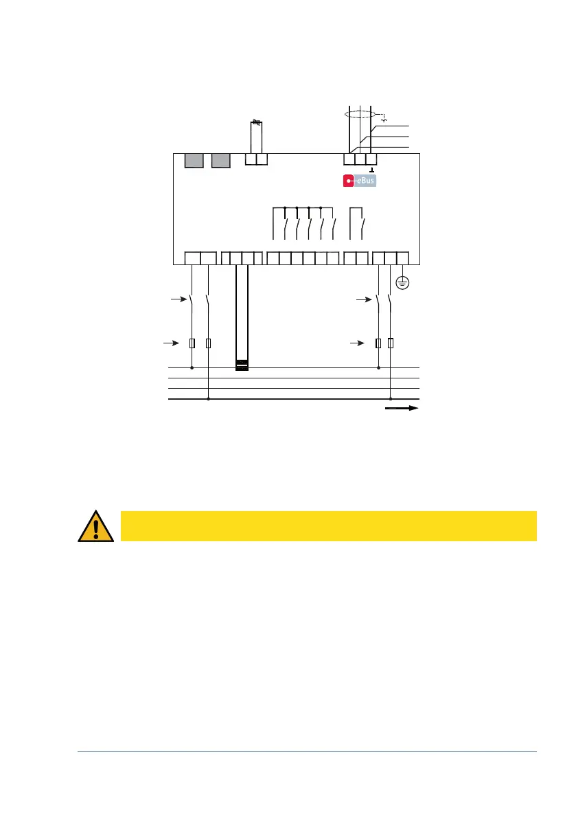
temperature probe
Temperaturfühler /
Relais /
Relay
C S
Module
Modul/
Display
OUT OUT
Stufen / Stages
multicomp D6-ESBSDS-1V1C6RO-7
zu weiteren Busteilnehmern
bzw. Leitungsabschluss /
to other bus devices
and line termination
max. C2 automat - max. C2 Automat
max. 1 A slow-blow - max. 1 A träge
max. C2 automat - max. C2 Automat
max. 1 A slow-blow - max. 1 A träge
circuit breaker - Trennvorrichtung
circuit breaker - Trennvorrichtung
PE
* For supply voltage, see type plate
* Versorgungsspannung siehe Typenschild
*
Netz / power
Messspannung / measuring voltage
Hauptstrom / main current
CAUTION
The coil voltage for the capacitor contactors and the measuring voltage must be drawn
from the same phase, as only the measuring voltage is monitored (to protect the contac-
tors from direct reset in case of short-term single-phase power failure).
2.2 Connection diagram