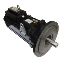
4.1.2 Encoder connection servo motor 7606910-40xx
WARNING
Adjustment of the measuring system
The measuring system of synchronous motors must be adjusted to the
respective inverter. Any mis-adjustment may lead to uncontrolled motor
response or complete failure of the motor.
In order to avoid any risk, the motor must be put into operation only in
no-load operation, without connection to the system.
Description View Pin Nr. Signal
View of the connector pins of the
resolver
5
9
1
6
1 R1 (Ref+)
2 R2 (Ref-)
3 S1 (Cos+)
4 S3 (Cos-)
5 S2 (Sin+)
6 S4 (Sin-)
7 GND
housing Shield
8, 9 Not connected
Figure 12: Terminal assignment of the resolver plug for servo motor 7606910-40xx
4.1.3 Connection of the brake and temperature monitoring for servo motor 7606910-40xx
Description View Pin Nr. Signal
View of the brake and tempera-
ture connector
4
5
1
2
1 Brake +
2 Brake -
3 Temp. +
4 Temp. -
5 Not connected
Figure 13: Pin assignment of the brake connection and temperature monitoring for servo motor 7606910-
40xx
39
CONNECTION
 Loading...