di - Parameter
60
Scanning
Noise
filter
digital
Input
logic
Select
signal
source
Control terminal strip
Parameter
di. 16
Input
trigger
Strobe
unit
Prozeß-
eingang
di. 15 di. 0 di. 2 di. 14 di. 17
di. 18
di. 19
Input
terminal
state
ru.14
Internal
input
state
ru.16
Digital
input setting
Input triggered:
0: B = A
1: B changes at the
pos. slope from A
A
B
Selection of the strobe signal:
1: input x forms
strobe signal
Strobe dependent:
0: not strobe dependent
1: strobe dependent
C
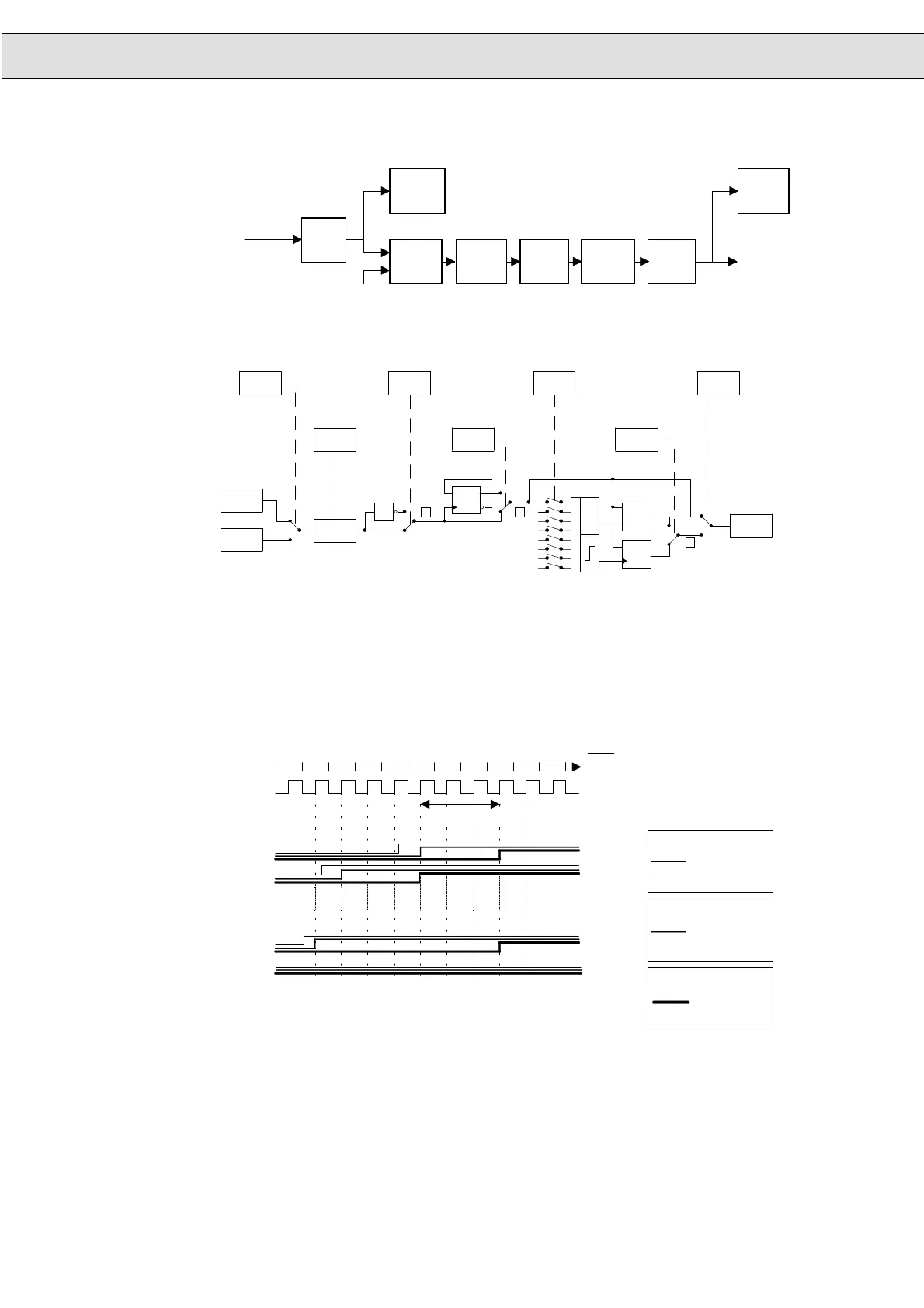
In general all parameters are preset, so that the input signal
(digitally filtered) directly passes through.
Strobe mode:
0: C = B at pos. slope
of strobe
1: C = B at strobe = 1
C = 0 at strobe = 0
di.16
Bit x
di.19
1
ru.14
Bit x
Input terminals
ru.16
Bit x
D
Q
Latch
Strobe
>
=
1
Clk
D
Q
Clk
DQ
_
Q
Input logic:
0: not inverted
1: inverted
Setting of the time
ffor the digital filter
(valid for all inputs)
di. 0
Signal source selection:
0: terminal
1: parameter di.16
di.15
Bit x
di. 2
Bit x
di.14
Bit x
di.18
Bit x
di.17
Bit x
Internal
input state
Digital
filter
The digital filter reduces the sensitivity to disturbances at the control inputs. di.0
adjusts the reaction time of the inputs. During the reaction time a constant input state
must be at
all
inputs, before a singal is accepted as valid.
1234567891011
t
4 ms
pos. slope =
sampling instant
for the input signals
I1
I2
I3
F
R
RST
Internal
control signal
without digital
filter
Internal control
signal / 16ms
digital filter
Filter time 16 ms
Signal
on the
control
terminal strip
Input Process
Noise Filter Digital
(di. 0)

 Loading...

