GA1060 Field bus master module Configuration
Project Engineering Manual, version: 1.1 / article no.: 1000296 11
© KEBA 2006
DAT8 = 16#0000
DAT9 = 16#0000
[IO.ONBOARD.KBUS:0.FM299:0.GA1060B:0.QSE:0.BANK8]
DAT2 = 16#0030
DAT3 = 16#1000
DAT4 = 16#0000
DAT5 = 16#0050
DAT6 = 16#0020
DAT7 = 16#0100
DAT8 = 16#0000
DAT9 = 16#0000
For user with a higher userlevel the following configuration entry is
available:
[IO.ONBOARD.KBUS:0.FM299A:0]
optional=0 / optional configuration:
/ 0 ... when the module is not available
/ an "Error" occurs
/ 1 ... when the module is not avialable
/ a "Warning" occurs
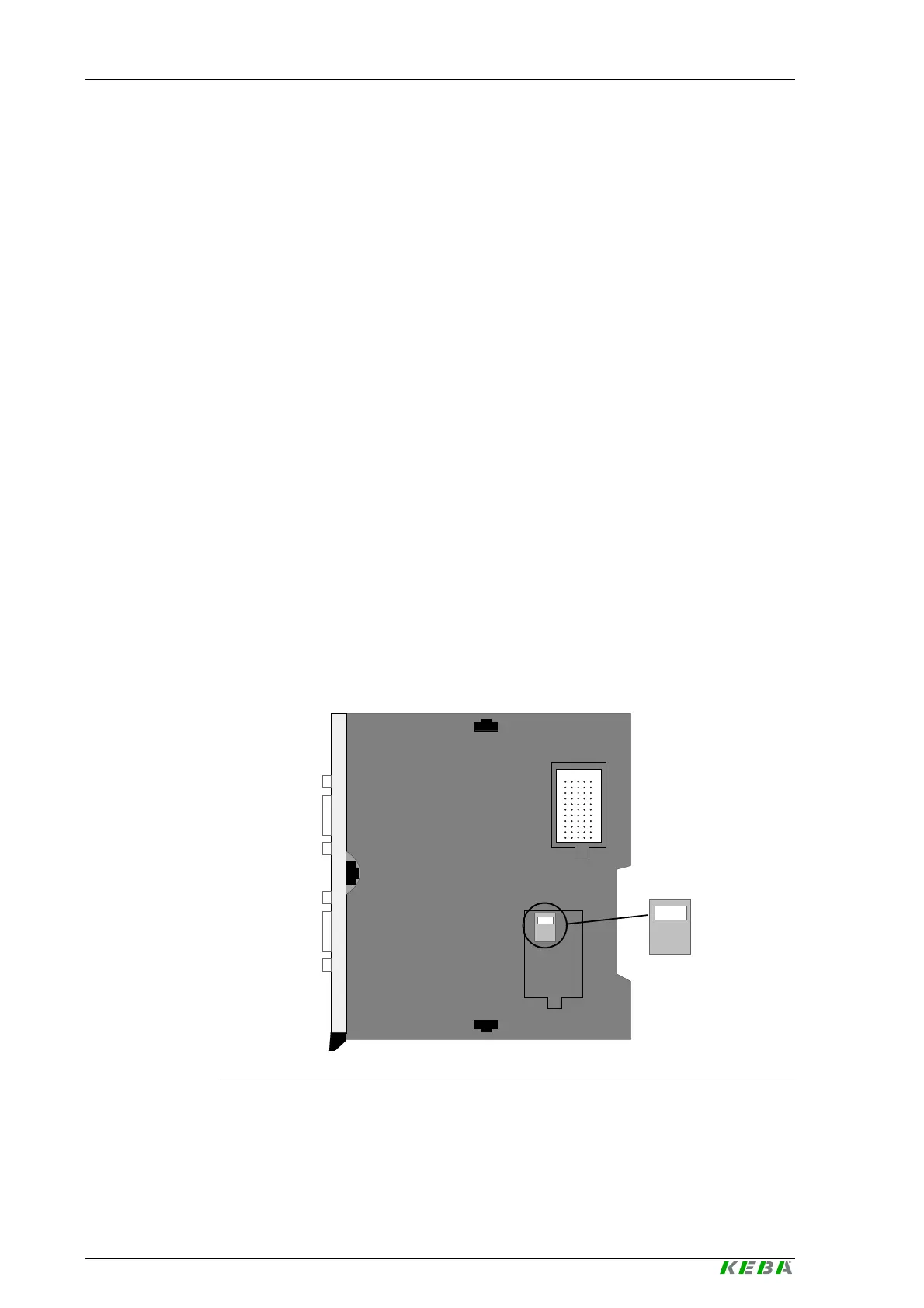
Setting the K-Bus address
The modules are addressed via the address switch. A maximum of two FM
299/A modules can be operated on one K2-200 control CPU.
The address switch is located on the right side underneath the lower cover.
The K-Bus plug is located underneath the upper cover.
ADR0
ADR1
Position of the address switch
On leaving the factory the FM 299/A module is set to address 0 and both
covers are closed.

 Loading...

