M5i | M5 STRIDER ELLIPTICAL
12
ASSEMBLY 3 OF 3: FINAL ASSEMBLY (CONTINUED)
5
6
7
8
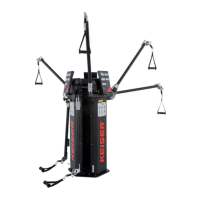
5. Attach the Handle/Hanger Assembly to the Top Frame
Shaft with a Hex Head Cap Screw and Large Washer
(Items 17 and 15) using a 13 mm Socket and Ratchet.
Torque: 23 Nm (17 ft-lbs). Insert the Aluminum Cap
(Item 7) into the Handle. Repeat step for the other
Handle/Hanger Assembly.
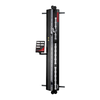
6. Align the holes of the Left Handle/Hanger Assembly
Bracket and the Left Pedal Mount. Insert one Hex Head
Cap Screw with Washer (Items 11 and 12) through the
screw holes, toward the Main Frame. Place a Washer
(Item 12) over the end of the Screw and install the
Elastic Lock Nut (Item 13) using a Ratchet with 13 mm
Socket and 13 mm Wrench. Torque: 23 Nm (17 ft-lbs).
Repeat this for the right-hand side (NOTE: The required
hardware is attached to the Right Pedal Mount).
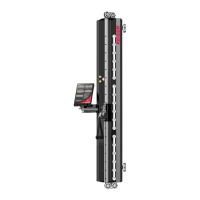
7. Final Assembly Checklist:
a. Computer Display is installed correctly and in
working order.
b. Handlebar Screws tightened evenly.
c. Handle to Top Frame Screws, torque: 23 Nm
(17 ft-lbs).
d. Handles to Hanger Pedal Mount Screws are
tightened.
e. Top Frame to Main Frame Screws, torque: 23 Nm
(17 ft-lbs).
f. Handle/Hanger Assembly to Hanger Pedal Mount
Screws, torque: 23 Nm (17 ft-lbs).
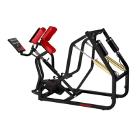
8. Apply Rust Inhibitor:
a. Right Rear Bracket Bearing at the base of the
Crank Arm.
b. Inner/outer Hanger Pedal Mount Bearings and
Bolts.
To position the Strider Elliptical at the desired
location, refer to the “Transport” section (page 14).
Handle/Hanger
Assembly
Top
Frame
Shaft
Hex Head
Cap Screw
Aluminum
Cap
LEFT
RIGHT
Large
Washer
LEFT
RIGHT
Washers
Elastic
Lock Nut
Left Pedal
Mount
Left Handle/
Hanger Assembly
Bracket
Hex Head
Cap Screws
a
a
b
b
c
b
d
e
f
Rust
Inhibitor
 Loading...