Verifying 1 Ω and 10 Ω resistance ranges
Check the normal resistance function by connecting accurate resistance values to the Series 3700A
analog backplane connector and verifying that the displayed readings fall within specified limits.
Do not exceed 300 V
PEAK
between INPUT HI and INPUT LO because instrument damage may
occur.
To verify normal resistance accuracy:
1. Connect the 1 Ω discrete resistor to the Series 3700A input.
2. For the dry circuit test points, enable the dry circuit resistance attribute (DRY+).
3. Select the SLOW integration rate with the RATE key.
4. Set the Series 3700A for the 1 Ω range, and make sure the FILTER is on. Enable OC+ (offset-
compensated ohms). Use OC+ for 1 Ω and 10 Ω range verification.
5. Recalculate reading limits based on actual discrete resistor resistance values.
6. Repeat using the 10 Ω discrete resistor on the 10 Ω range.
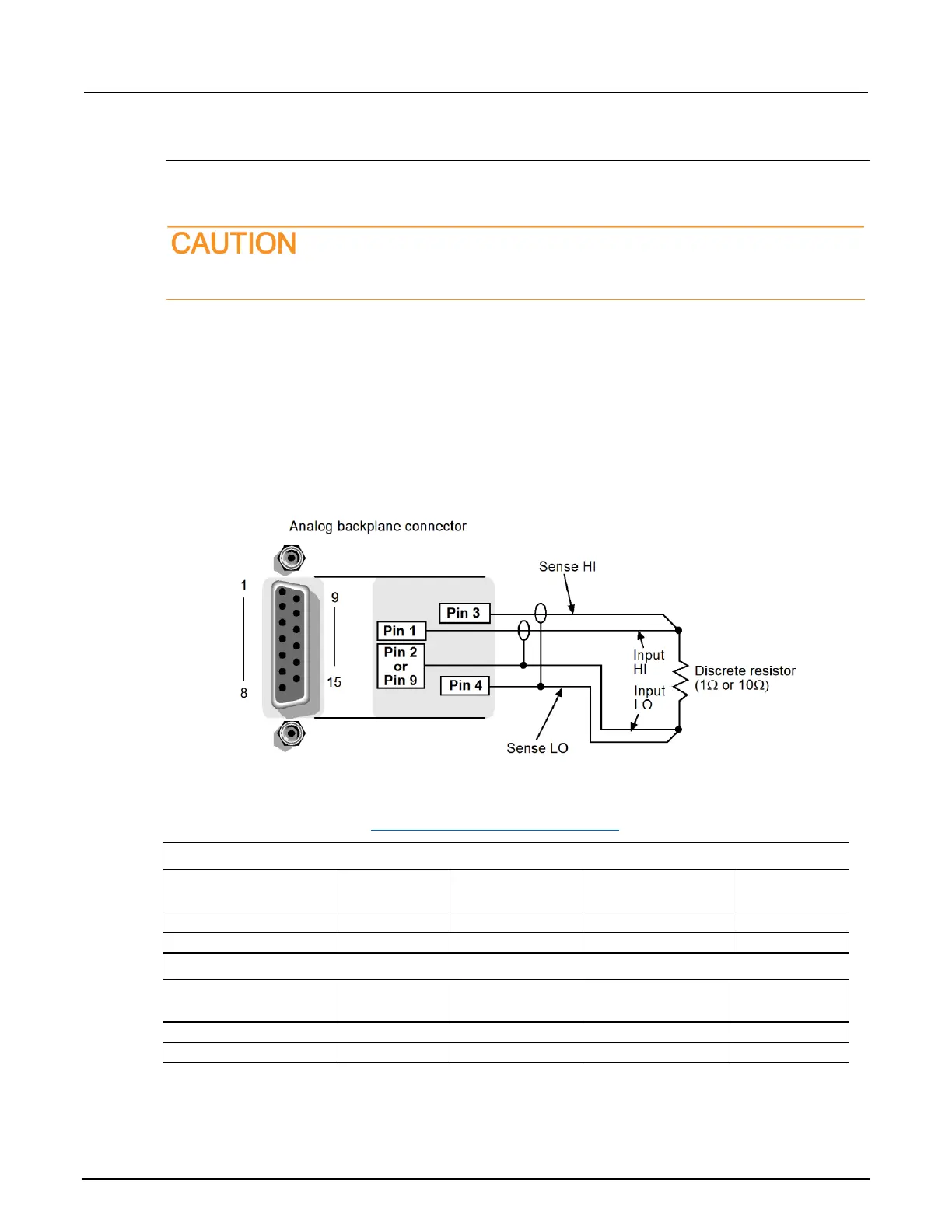
Figure 169: Verifying discrete resistance
Discrete resistance verification data
Use the following values to verify the performance of the Series 3700A. Actual values depend on
published specifications (see Calculating resistance reading limits (on page B-4)).
 Loading...


