To verify dry circuit resistance accuracy:
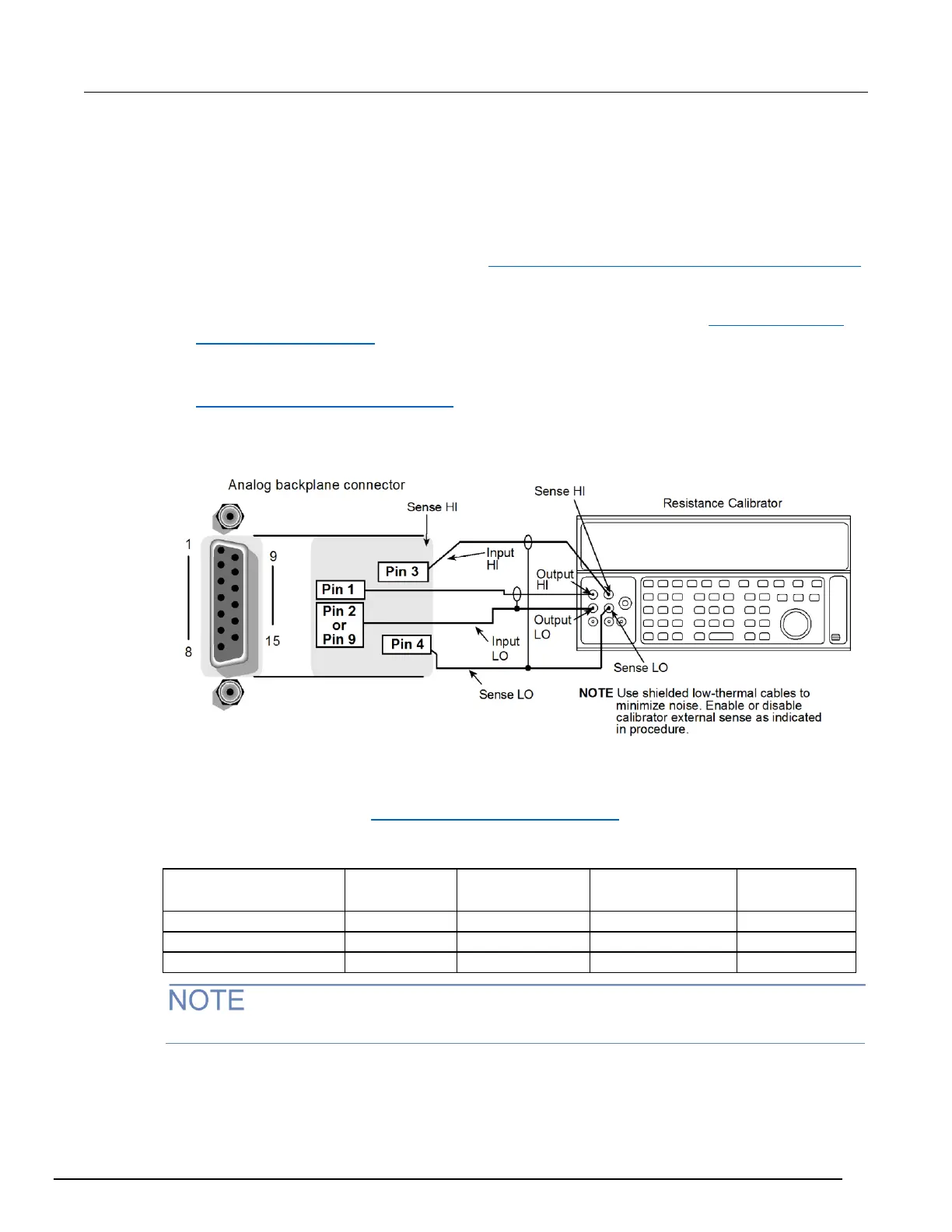
1. Using shielded, Teflon-insulated or equivalent cables in a 4-wire configuration, connect the Series
3700A INPUT and SENSE pins to the calibrator as shown for 100 Ω to 10 MΩ ranges.
2. Set the calibrator for 4-wire resistance with external sense on.
3. Select the Series 3700A 4-wire resistance function.
4. Enable dry circuit resistance function (see Enable or disable dry circuit ohms from the front panel
(on page 4-65)).
5. Set the Series 3700A for the 100 Ω range, and make sure the FILTER is on. Enable OC+ (offset-
compensated ohms). Use OC+ for 100 Ω and 1 kΩ range verification. See Enabling/disabling
offset-compensated ohms (on page 4-67) in the User's manual.
6. Recalculate reading limits based on actual calibrator resistance values.
7. Source the nominal full-scale resistance values for the 100 Ω to 2 kΩ ranges summarized in the
Dry circuit resistance verification data (on page B-17) table. Verify that the readings are within
calculated limits.
Figure 168: Resistance verification
Dry circuit resistance verification data
Use the following values to verify the performance of the Series 3700A. Actual values depend on
published specifications (see Calculating resistance reading limits (on page B-4)).
 Loading...


