To verify normal resistance accuracy:
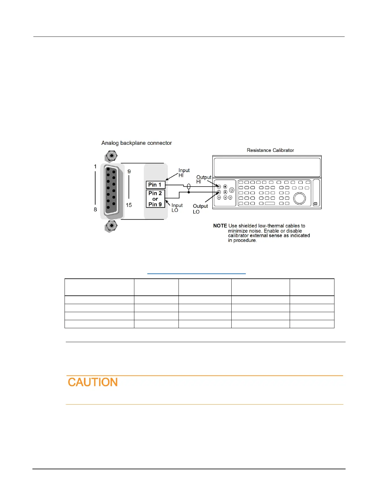
1. Using shielded, Teflon-insulated or equivalent cables in a 2-wire configuration, connect the Series
3700A INPUT and SENSE pins to the calibrator as shown in the "2-wire resistance verification
diagram" below.
2. Disable the external sense on the calibrator.
3. Set the Series 3700A to the 2-wire resistance function, set to the proper range.
4. Source a nominal 100 kΩ to 100 MΩ resistance value. Recalculate the limits based on the actual
value of the resistor and verify that the reading is within the calculated limits.
Figure 167: 2-wire resistance verification
2-wire resistance verification data
Use the following values to verify the performance of the Series 3700A. Actual values depend on
published specifications (see Calculating resistance reading limits (on page B-4)).
Verifying dry circuit resistance
Check the dry circuit resistance function by connecting accurate resistance values to the Series
3700A analog backplane connector and verifying that the displayed readings fall within specified
limits.
Do not exceed 300 V
PEAK
between INPUT HI and INPUT LO because instrument damage may
occur.
 Loading...


