Series 3700A System Switch/Multimeter Reference Manual Appendix B: Verification and adjustment
3700AS-901-01 Rev. D/June 2018 B-15
7. Source the nominal full-scale resistance values for the 100 Ω to 10 MΩ ranges summarized in the
4-wire resistance verification data (on page B-15) table. Recalculate the limits based on the
actual value of the resistor and verify the reading is within the calculated limits.
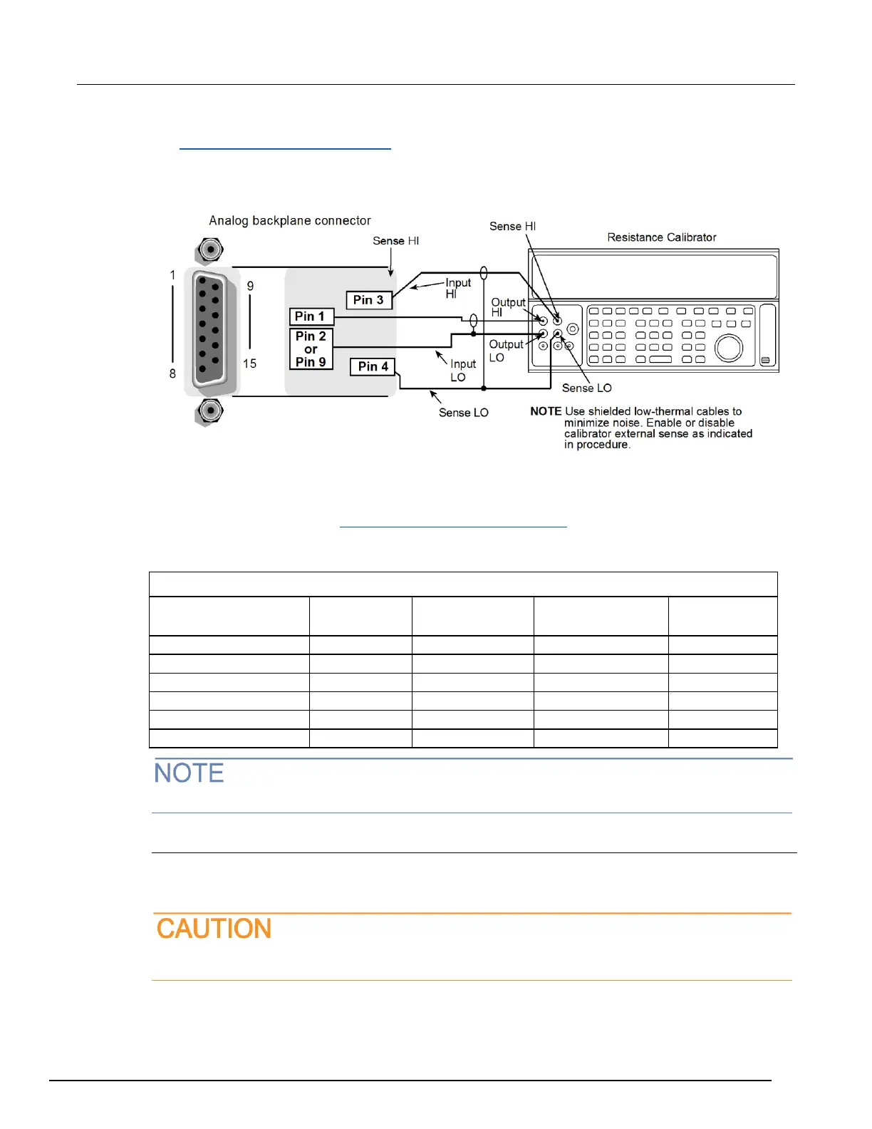
Figure 166: Resistance verification
4-wire resistance verification data
Use the following values to verify the performance of the Series 3700A. Actual values depend on
published specifications (see Calculating resistance reading limits (on page B-4)).
Connect to the Fluke 5700A calibrator
The asterisk (*) designates the ranges that offset compensation is being used.
Verifying 2-wire resistance
Check the normal resistance function by connecting accurate resistance values to the Series 3700A
analog backplane connector and verifying that the displayed readings fall within specified limits.
Do not exceed 300 V
PEAK
between INPUT HI and INPUT LO because instrument damage may
occur.
 Loading...


