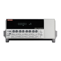
1-12 Getting Started Model 6485 and 6487 User’s Manual
5 TRIGGER LINK
Eight-pin micro-DIN connector for sending and receiving trigger pulses among connected instruments.
Use a trigger link cable or adapter, such as Models 8501-1, 8501-2, 8502, and 8503.
6 RS-232
Female DB-9 connector for RS-232 operation. Use a straight-through (not null modem) DB-9 shielded
cable.
7 IEEE-488
Connector for IEEE-488 (GPIB) operation. Use a shielded cable, such as Models 7007-1 and 7007-2.
8Power module
Contains the AC line receptacle and power line fuse. The instrument can be configured for line volt-
ages of 115V and 230VAC (nominal) at line frequencie
s of 50 or 60Hz automatically and over the bus.
Changing line voltages requires changing fuses.
Analog output
The Model 6485 has an analog output on the rear panel. The ANALOG OUT provides a
scaled, inverting ±2V output. A full-scale reading corresponds to ±2V output. See “Ana-
log output,” page 2-14 in for full details on analog output operation.
Display
Readings can be displayed in engineering units or scientific notation. Annunciators indi-
cate various states of operation. See “Model 64
85 front panel summary,” page 1-8 for a
complete listing of display annunciators.
NOTE Cha
nging the display resolution is not allowed if displaying readings in
scientific notation.
The Display and Keys Test allows you to test display digit segments and annunciators, and
check the
functionality of front panel keys. These tests are accessed through the MENU.
Status and error messages
Status and error messages are displayed momentarily. During operation and program-
ming, you will encounter a number of front panel messages. Typical messages are either
of
status or error variety, as listed in Appendix B of the Model 6485 Instruction Manual.

 Loading...