Model 6485 and 6487 User’s Manual Connections 2-15
Figure 2-15
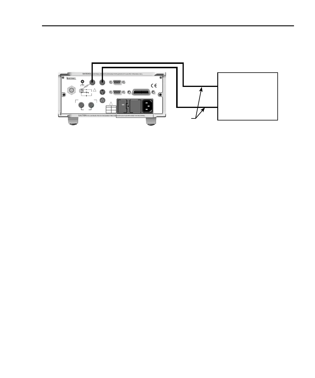
Typical Model 6487 analog output connections
Test Lead
120
LINE RATING
50, 60Hz
50 VA MAX
INPUT
(CHANGE IEEE ADDRESS
WITH FRONT PANEL MENU)
IEEE-488
CAT I
TRIGGER LINK
RS-232
MADE IN
U. S.A .
ANALOG OUT
DIGITAL I/O
INTERLOCK
505V
MAX
V-SOURCE OUTPUT
505V PK TO CHASSIS
LO HI
!
!
FUSE LINE
630mAT
(SB)
100 VAC
120 VAC
315mAT
(SB)
220 VAC
240 VAC
505V PK
505V PK
505V PK
Model 6487 Rear Panel
Measuring Device
(i.e. Chart recorder)
LO
HI
Measurement considerations
There are a variety of factors to consider when making low-level measurements. These
considerations are summarized in Table 2-1 and are detailed in Appendix C of the Model
6485 Instruction Manual and Appendix G of the
Model 6487 Reference Manual, as well as
in Appendix B of this manual. For comprehensive info
rmation on all measurement consid-
erations, refer to the Low Level Measurements
handbook, which is available from Keithley
Instruments.

 Loading...


