Series 2600 System SourceMeters Reference Manual Digital I/O Port 10-5
Return to Section 10 topics 2600S-901-01 Rev. A / May 2006
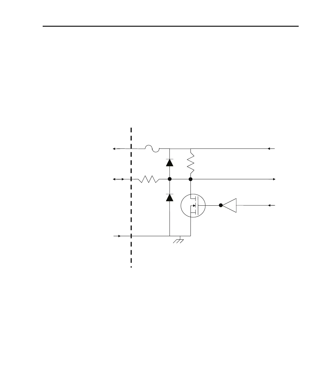
Figure 10-2
Digital I/O port configuration
DIGITAL I/O INTERFACE (All Series 2600 Models):
Connector: 25-pin female D
Input/Output pins: 14 open-drain I/O bits
Absolute maximum input voltage: 5.25V
Absolute minimum input voltage: -0.25V
Maximum logic low input voltage: 0.7V @ +850mA
Minimum logic high input voltage: 2.1V @ +570mA
Maximum source current (flowing out of digital I/O bit): +960mA
Absolute Maximum sink current (flowing into digital I/O bit): -11.0A
Maximum Sink Current @ Maximum Logic Low Voltage (0.7V): -5.0mA.
Read by firmware
5.1kW
Rear panel
100W
Written by firmware
+5VD
600mA solid state
fuse
DIGITAL I/O pin
(on DIGITAL I/O connector)
GND pin
(on DIGITAL I/O connector)
+5V pin
(on DIGITAL I/O connector)
Controlling digital I/O lines
Although the digital I/O lines are primarily intended for use with a device handler
for limit testing, they can also be used for other purposes such as controlling
external logic circuits. You can control lines either from the front panel or via
remote as follows.