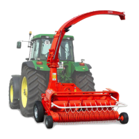
5.9 Metalldetector C3000
1. The lifting spindle 1 is first connected to the cam plate 2 and set at an angle of
5° [position 0). In this position, the tension roller is in the middle of the cam
plate.
2. The position switch 28A is then in the centre.
3. The operating lever 5 is likewise in the centre position (ball clutch).
4. After these basic adjustments, the distance between connections 6 and 7 is a
dimension X.
5. This distance X can be adjusted on spring cylinder 8 by means of nut 9. Spring
cylinder 8 is then connected to operating lever 5. The two adjusting screws 10
and 11 act as stops to limit the forward and reverse travel of the gear lever.
Adjustment: Set operating lever in end position by means of the spring
cylinder, turn screw 112 turn anti clockwise and lock with a lock nut.
6. Spring 12 is particularly critical for correct V-belt tension. It should therefore be
checked regularly.
7. The position switch 28A detects the position of the lifting spindle I: forwards,
neutral or reverse. The correct position is when the tension roller 3 is the
Same distance from the carn plate 2 in forward or reverse.drive. '
8. The limit switch 28B cuts off the current to the lifting spindle 1 just before it
reaches its end position. (Versions with detector only).
 Loading...