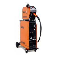
TECHNICAL SERVICE MANUAL FOR KEMPOWELD
GENERAL MAINTENANCE OF KEMPOWELD
Maintenance of Kempoweld power source will normally consist of general cleaning
of unit with soft brush and vacuum cleaner, and checking of wearing for parts like:
switches,connectors, potentiometers and fuses. NOTE! If you use compressed air
for cleaning, there is a risk that dirt is packed even more tightly into gaps of
connectors or components, so be carefull with those parts!
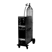
Maintenance of the wire feeder and mig gun will normally consist of general
cleaning and change of consumable parts like: contact tube, contact tip,
contact tip adapter, gas nozzle, wire conduit, feeding rolls, guide tubes, and gear
wheel.
The number of machines in will determine to what extend consumable- and spare
parts will be stocked.
WARNING
Watch out for the mains voltage! Disconnect the power source from mains voltage
before removing cover plates or any testing or measurement and before
troubleshooting look for signs of over heating, fractures and damages from internal
components and power semiconductors.
TROUBLESHOOTING CHART
TROUBLE CAUSE REMEDY
The KEMPOWELD won´t start at all,
any of the auxiliary devices won´t
start.The signal lamps of machine
are not switched on.
Blown fuse in mains supply voltage.
Faulty mains cable.
Broken main switch.
Faulty auxiliary transformer T002 or
bad connection in connector X9,
400V or 0V.
Blown fuse F001 8A.
Check all three supply voltage
phases; check fuses.
Check mains voltage from terminal
block X001, repair cable if needed.
Check the main supply voltage
before and after main switch, change
switch if needed.
Check transformer, repair
transformer connection or change
if needed.
Check fuse and change if needed.
The wire feeding unit K200/400
won´t work.
Faulty connection in control lines.
Blown fuse F001 8A.
Broken PCB.
See, TABLE FOR CONTROL
LINES, table 1.
Check/change fuse F001.
See, TROUBLE SHOOTING FOR
PCBs appendix 1.
 Loading...