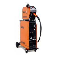
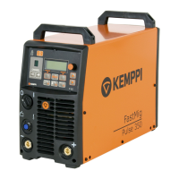
TECHNICAL SERVICE MANUAL FOR KEMPOWELD
TROUBLESHOOTING CHART
TROUBLE CAUSE REMEDY
The cooling unit don´t start or pilot
lamp Hw3 lacking water pressure is
iluminated.
Blown fuse F002 2A.
Auxiliary transformer T002.
Pressure switch S005
5µF capacitor C001.
Broken PCB.
Check and change the fuse if
needed.
Check the voltage from transformer
in the terminal block between 2.1
and 2.2, it should be 230v.
Check the voltage over the pressure
guard or from PCB A002 X2/1 and
X2/8; enough pressure 0V and lack
of pressure c. 5V.
Check and change the capacitor if
needed.
See, TROUBLE SHOOTING FOR
PCBs appendix 1.
The solenoid valve Y001 don´t work. Faulty solenoid valve or PCB A001. Check the 24 VDC from connector
X3/5 and X3/6, change valve or
PCB.
Wire feeding motor don´t work. Blown fuse F001 8A
The control cable between feeder
and power souce is broken or it is
not properly tightened.
Faulty motor or PCB A001in
K200/400.
Broken PCB.
Check/change the fuse if needed.
Check and repair the control cable if
needed. See table 1.
Check the motor voltage from A001
X4/12 and X4/13 max. is c. 24 VDC,
if it´s all right motor is faulty.
See, TROUBLE SHOOTING FOR
PCBs appendix 1.
Welding quality is bad:
- arc is not stable
- there are lot of spatters
- bad arc start
- not enough arc voltage
One phase is missing.
Faulty main transformer T001.
Faulty main switch S001 or contactor
K001.
Shielding gas is missing.
Gas hose of the gun is leaking or
connection is loose.
Broken diode in the secondary.
rectifier G001.
Check all phases from the therminal
block X001. Change mains fuse if
needed or tighten mains cables.
Check that voltages are symmetric
over the three spools of T001.
Variation of voltage is depending on
voltage selection and load; normally
it is between 10 VAC and 32 VAC.
OCV variation range is 11 VAC
to 35 VAC
Measure first main switch if it is all
right check the contactor.
Check the valve according the
instructions mentioned above.
Check/repair the mig gun.
Check and change diode(bridge)
if needed.
 Loading...
