SERVICE MANUAL
KEMPACT RA_V_1.2
30 (40)
Kemppi Oy
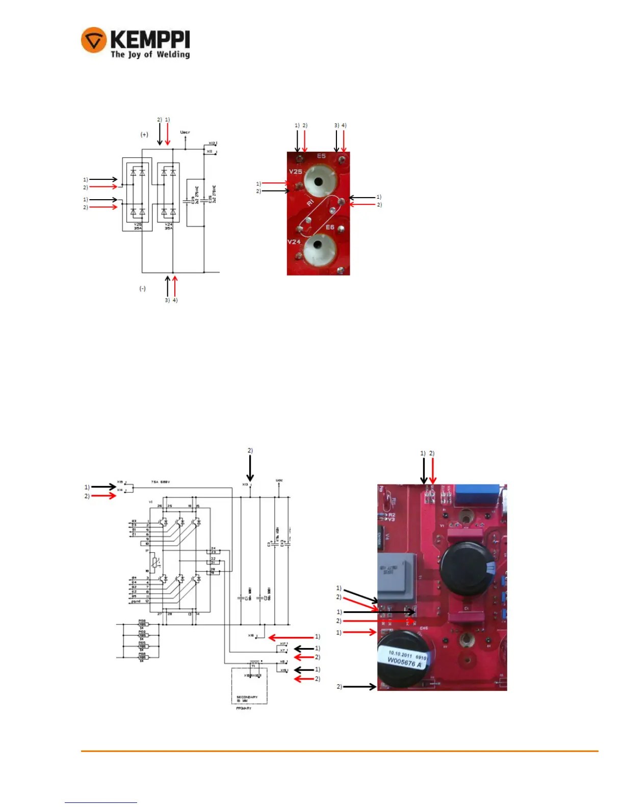
8.1.2. IGBT module V1
• IGBT module can be tested by multimeter if using the diode tester function. Module holds six diodes and in many
cases they may be defective if IGBT is damaged
• When measuring IGBT unit diodes you must disconnect other end of main transformer (X7)
o After measuring connect other end (X7) back
Measurings:
1) Positive test pole (1, red) to connector X16, negative test pole (1, black) to connectors X7, X8 and X14 one at time
Result: 0,3…0,6diodes Ok
2) Negative test pole (2, black) to connector X13, positive test pole (2, red) to connectors and X7, X8 and X14 one at time
Result: 0,3…0,6diodes Ok

 Loading...