8 / 1921710E / 0040
English
Sizes of mains cables and fuse ratings for the machine at 100 % ED duty cycle are specified below:
Kempomat 2001: Rated voltage 240 V, Fuse, delayed 20 A, Connection cable 3 × 2,5 S mm
2
Kempomat 2501: Rated voltage 240 V, Fuse, delayed 25 A, Connection cable 3 × 4,0 S mm
2
In cables of S type there is a protective grounding conductor, coloured green/yellow.
Welding and return current cables
In enclosed table displays typical loading capacities of rubber insulated copper cables, when ambient temperature
is 25 °C and conductor surface temperature is 85 °C.
Don´t overload welding cables over permissible values due to voltage losses and heating.
Fasten the earth clamp of the return current cable carefully, preferably directly onto the work piece.
The contact surface area of the clamp should be as large and steady as possible. Clean the contact surface from
paint and rust.
Installation of wire feeding
Accessories according to wire feed
Wire feed rolls are available within plain groove, knurled groove and with U groove for different purposes.
Feed roll with plain groove:
Universal feed roll for welding of all kinds of wires
Feed rolls with knurled groove:
Special feed roll for cored wires and steel wires
Feed rolls with U groove:
Special feed roll for aluminium wires
Wire feed rolls have two grooves for different filler wire
diameters. Correct wire groove is selected by moving
the selection washer from one side to the other in the
feed roll.
Feed rolls and wire guide tubes have colour codes in order to simplify identification (see table on page 4).
On delivery, the Kempomat 2001 is equipped with white feed rolls with plain groove and with white wire guide tubes
for welding filler wires of 0.6 and 0.8 mm (0.030"). Kempomat 2501 is equipped with red feed rolls with plain groove
and orange wire guide tubes for welding filler wires of 0.9-1.2 mm (0.035", 0.045" and 0.052").
Mounting of MIG welding gun
In order to ensure problem-free welding, check the operation instructions of the gun that wire guide tube and
contact tip of gun are in accordance with the manufacturer´s recommendation, and suitable to be used for wire feed
diameter and type in question. An overly tight wire guide tube could cause excessive stress on the wire feed unit,
resulting in disturbances in wire feed.
Screw snap connector of gun tightly, to avoid voltage losses on connecting surface. Aloose connection
will heat gun and wire feeder unit. Check after tightening, that guide tube inside connector is not in contact
with feed rolls.
Mounting and locking of wire reel
Cable cross-section Duty cycle ED Voltage loss / 10 m
Cu 100 % 60 % 30 % for 100 A
25 mm
2
180 A 230 A 330 A 0.7 V
35 mm
2
225 A 290 A 410 A 0.5 V
Feed rolls
colour filler wire ø mm (inch)
white 0.6 and 0.8 (0.030)
red 0.9/1.0 and 1.2 (0.035, 0.045 and 0.052)
Guide tubes
colour filler wire ø mm (inch)
white 0.6 and 0.8 (0.030)
orange 0.9-1.6 (0.035, 0.045 and 0.052)
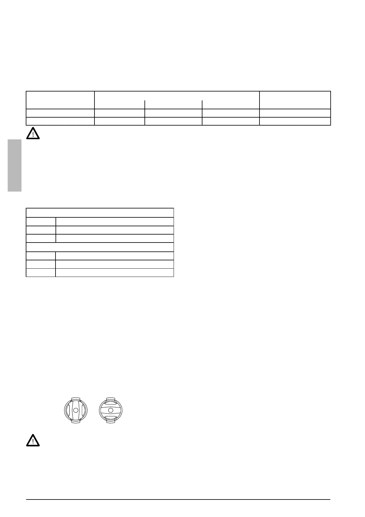
Release locking nails of wire reel hub by turning lock-
ing knob to the position OPEN.
Mount the reel at its place. Note rotating direction of reel!
Turn the locking knob to the position LOCKED.
Check filler wire reel for no protruding parts, which could e.g. chaff against chassis or door of wire feeder unit.
Dragging parts could expose chassis of wire feeder unit under voltage.
Automatic wire feed to gun
Automatic wire feed makes change of wire reel quicker. In reel change, the pressure of feed rolls need not be
released and filler wire goes automatically to correct wire line.
Make sure that the groove of feed roll matches the diameter of welding wire used. Feed roll groove is selected
by moving the groove selection washer.
LOCKED OPEN
 Loading...