17
© Kemppi Oy / 1736
EN
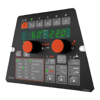
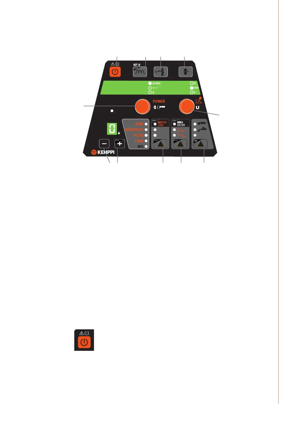
3.2 Layout
NOTE! The button layout is the same in both, XF 37 and XF 38 panels.
XF 37
W007241
CH REMOTE
CHANNEL
PANEL
4T
2T
1. 3.
2.
4.
5. 6.
7. 8. 9.
10.
11.
1. ON/OFF button
2. Activates MIG welding dynamics (short press)
Selects the active wire feeder, if several wire feeders exist (long press)
3. Gas test
4. Wire inch
5. Selects the previous memory channel
6. Selects the next memory channel (short press)
Locks selected memory channel (long press)
7. Selects welding gun trigger mode (short press) or turns MatchLog function ON/OFF
8. Selects crater ll, hot start (short press) or MMA/CC/CV (long press)
9. Selects panel control, gun control unit or hand-held control unit (short press).
Turns memory channel remote selection ON/OFF (long press).
10. Power control knob
11. Arc length and voltage control knob.
Automatic weld data display
Last recorded welding values are displayed post welding.
Voltage display
Voltage display will show arc voltage if selected from the setup panel. Voltage display's last
dot indicates that arc voltage display is selected (for example 23.5. V). If arc voltage feature is
not used, pole voltage of the power source is shown.
3.3 Button functions
3.3.1 ON/OFF button (1)
XF 37
W007241
CH REMOTE
CHANNEL
PANEL
4T
2T
Short press: control panel returns to initial display.
Long press: control panel is turned ON or OFF.
NOTE! When wire feeder XF 37 / XF 38 control panel is turned ON, also the power source control
panel X 37 turns on and links automatically to this wire feeder.
 Loading...